Snowflake machine roller

A technology of snowflake machine and roller, which is applied in ice making, lighting and heating equipment, leisure ice making, etc. It can solve unresolved technical problems and other problems, and achieve the effect of reasonable design, improved condensation effect and consistent hardness

Active Publication Date: 2017-06-13
安派智厨(浙江)有限公司
View PDF10 Cites 1 Cited by
  • Summary
  • Abstract
  • Description
  • Claims
  • Application Information

AI Technical Summary

Problems solved by technology

[0004]Although the above-mentioned solution has many advantages above, the above-mentioned solution does not solve the above-mentioned technical problems. Therefore, it is urgent to design a better sealing snow machine roller

Method used


Image

  • Snowflake machine roller
  • Snowflake machine roller
  • Snowflake machine roller

Examples


Embodiment Construction

[0032] The following are specific embodiments of the invention and in conjunction with the accompanying drawings, the technical solutions of the present invention are further described, but the present invention is not limited to these embodiments.

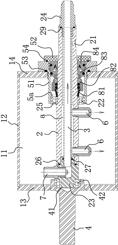
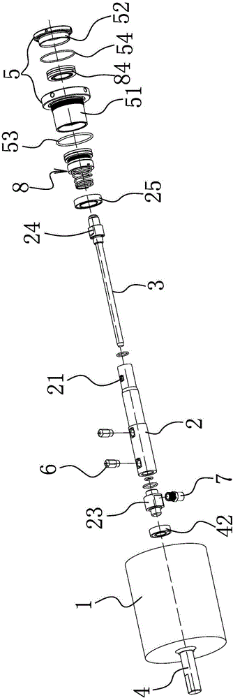
[0033] Such as Figure 1-2 As shown, the roller of this snowflake machine includes a roller body 1 with a cavity 11 inside, and the roller body 1 includes a roller ring 12, a left end cover 13 is provided at one end of the roller ring, and a right end cover 14 is provided at the other end of the roller ring. The axial center of the left end cover 13 is provided with a left mounting hole, and the axial center of the right end cover 14 is provided with a right mounting hole. The axis line of the left mounting hole coincides with the axis line of the right mounting hole. 13 joints are welded and connected, and the joints of the roller ring 12 and the right end cover 14 are welded and connected, that is, leakage at the joints is avoid...


PUM


Abstract

The invention relates to a snowflake machine roller. The snowflake machine roller comprises a roller main body, wherein a chamber is formed in the roller main body; the roller further comprises a drum-shaped rotating shaft and a liquid return pipe; one end of the drum-shaped rotating shaft is closed; the liquid return pipe is inserted into the drum-shaped rotating shaft; the two ends of the drum-shaped rotating shaft are in sealing connection with the two ends of the liquid return pipe; a liquid entering sealing chamber is formed between the drum-shaped rotating shaft and the liquid return pipe; a motor connecting shaft is penetrated through one end of the roller main body; one end of the drum-shaped rotating shaft is inserted into the roller main body and is in rotating connection with an inner end of the motor connecting shaft; a drum-shaped end cover part is penetrated through the other end of the roller main body; the other end of the drum-shaped rotating shaft is inserted into the drum-shaped end cover part; the other end of the drum-shaped rotating shaft extends out of an outer end of the drum-shaped end cover part; at least one refrigerant fluid nozzle is arranged on the drum-shaped rotating shaft; a liquid return nozzle which is communicated with the liquid return pipe is arranged at the closed end of the drum-shaped rotating shaft; the drum-shaped rotating shaft and the drum-shaped end cover part are in rotating connection with each other; a mechanical sealing mechanism is arranged between the drum-shaped rotating shaft and the drum-shaped end cover part.

Description

technical field [0001] The invention belongs to the technical field of snowflake machines, and in particular relates to a snowflake machine roller. Background technique [0002] The sealing method of the snowflake machine drum in the existing market adopts O-ring for axial sealing. When the drum is stationary, the O-ring can play a good sealing effect, but when the drum is running and the compressor is running, there is a gap between the drum and the sealing ring. Relative movement, and there is high pressure inside the drum, the O-ring cannot achieve a good sealing effect, resulting in leakage of Freon, resulting in a decline in cooling effect or failure to cool after a long time. [0003] For example, Chinese patent literature discloses a flavored snowflake machine [Application No.: 201420420841.3], which includes a snow-making device, which includes a snow-making drum evaporator, a liquid storage box, a cutter, a water inlet, a water inlet valve, a transmission The motor...

Claims


Application Information

Patent Timeline
Patent Type & Authority Applications(China)
IPC IPC(8): F25C3/04
CPCF25C3/04
Inventor 陈祥利杨永富
Owner 安派智厨(浙江)有限公司
Why Eureka
Try Eureka