Planar and spatial feature-based laser radar and camera automatic joint calibration method

A technology of lidar and spatial features, which is used in the re-radiation of electromagnetic waves, image data processing, measurement devices, etc.

Pending Publication Date: 2019-05-31
TZTEK TECH
View PDF5 Cites 16 Cited by
  • Summary
  • Abstract
  • Description
  • Claims
  • Application Information

AI Technical Summary

Problems solved by technology

The target is generally located in an open scene, and AI technology is used to identify and locate the target in th

Method used


Image

  • Planar and spatial feature-based laser radar and camera automatic joint calibration method

Examples


Embodiment Construction

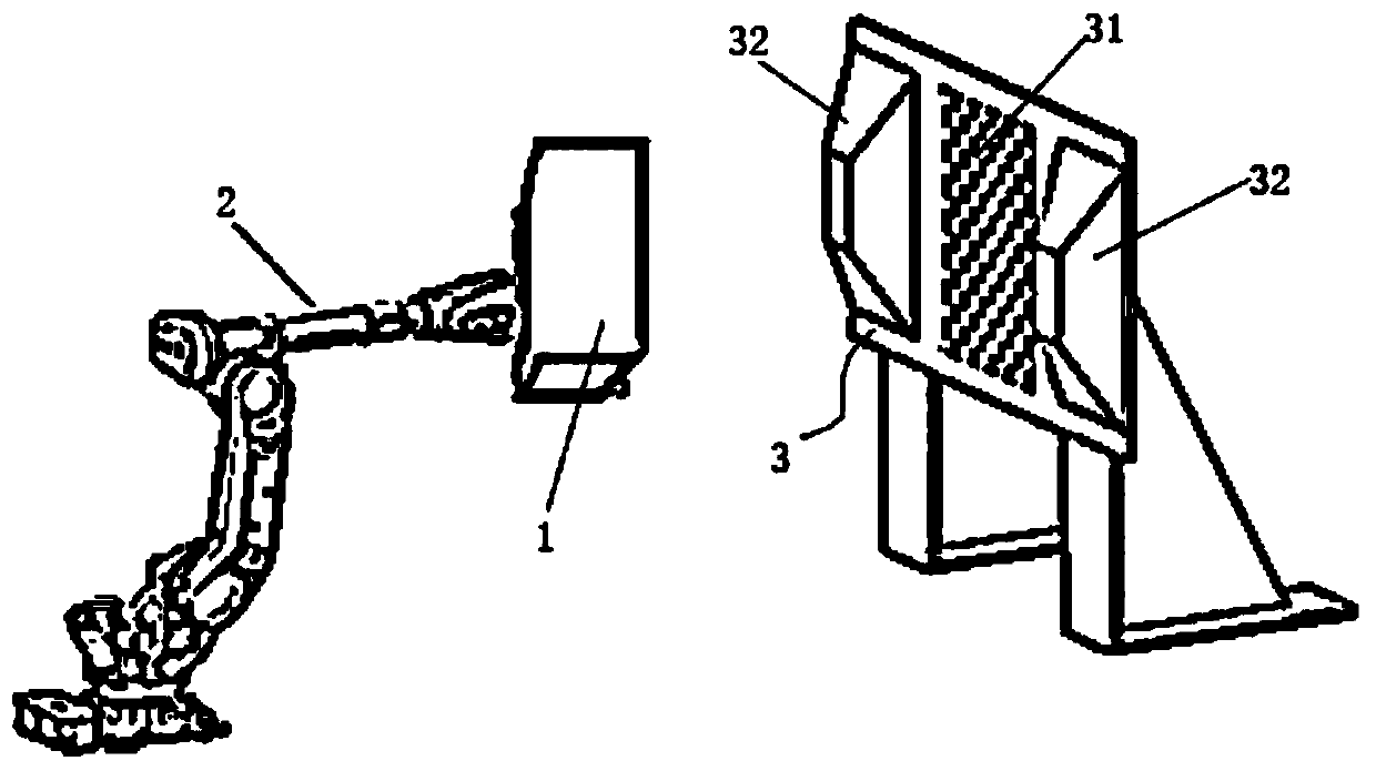
[0012] Automatic joint calibration method of lidar and camera based on plane and space features, see figure 1 : Install the laser radar and the camera on the equipment to be calibrated 1, and then fix the equipment to be calibrated 1 on the output end of the six-axis mechanical arm 2. In the initial state, a calibration plate 3 is set directly in front of the laser radar and the camera. The calibration plate 3 is designed with two geometric features, plane calibration feature 31 and space calibration feature 32; the camera extracts the calibration points in the plane calibration feature 31, and the laser radar extracts the calibration points in the space calibration feature to drive the output end of the six-axis robot arm Drive the equipment to be calibrated to move according to the set trajectory, obtain the corresponding calibration plate image through the camera, and calibrate the internal and external parameters of the camera through Zhang Zhengyou’s calibration method; us...


PUM


Abstract

The invention provides a planar and spatial feature-based laser radar and camera automatic joint calibration method. According to the method, a laser radar and a camera are separately adopted to position planar and spatial features designed on a calibration object, so that the laser radar and the camera can be fast and reliably calibrated. The laser radar and the camera are mounted on a device tobe calibrated, and then, the device to be calibrated is fixed at the output end of an six-axis mechanical arm; in an initial state, a calibration plate is arranged just in front of the laser radar andthe camera, and two kinds of geometric features, namely, planar calibration features and spatial calibration features are designed on the calibration plate; and the camera extracts calibration pointsfrom the planar calibration features so as to use the calibration points, and the laser radar extracts calibration points from the spatial calibration features so as to use the calibration points; and the output end of the six-axis mechanical arm is driven to drive the device to be calibrated to move according to a set trajectory; the camera obtains a corresponding calibration plate image; and the internal and external parameters of the camera are calibrated by the Zhang Zhengyou calibration method.

Description

technical field [0001] The invention relates to the technical field of automatic driving, in particular to an automatic joint calibration method of laser radar and camera based on plane and space features. Background technique [0002] The fusion of laser radar and camera information is currently widely used in the perception and automatic navigation systems of unmanned vehicles and autonomous mobile robots to complete a series of computing tasks such as SLAM positioning, target recognition and tracking, and obstacle detection. The joint calibration of lidar and camera is the basis of information fusion between the two. [0003] The current common calibration method is to use lidar and camera to identify and locate the target object in the calibration scene, and complete the joint calibration of the two sensors through the position of the target object in the two sensors. The target is generally located in an open scene, and AI technology is used to identify and locate the ...

Claims


Application Information

Patent Timeline
IPC IPC(8): G01S7/497G06T7/80G01S17/42
Inventor 刘军传田乃鲁翁海峰刘克志
Owner TZTEK TECH
Why Eureka
Try Eureka