
Automatic fuel calibration device and method for electric injection system

An automatic calibration and fuel technology, which is applied to fuel injection devices, measuring devices, charging systems, etc., can solve the problems of long time required and low efficiency, and achieve the effect of saving time.

Pending Publication Date: 2020-11-20
HUAYI MECHANICAL & ELECTRICAL CO LTD
View PDF0 Cites 0 Cited by
  • Summary
  • Abstract
  • Description
  • Claims
  • Application Information

AI Technical Summary

Problems solved by technology

[0007] In the past, almost every step was done manually, and the efficiency was low. It took about a day to calibrate a basic fuel injection pulse width table. If the table is larger, it will take longer

Method used


Image

  • Automatic fuel calibration device and method for electric injection system
  • Automatic fuel calibration device and method for electric injection system
  • Automatic fuel calibration device and method for electric injection system

Examples


Embodiment Construction

[0048] Below in conjunction with accompanying drawing, structural principle and working principle of the present invention are specifically described:

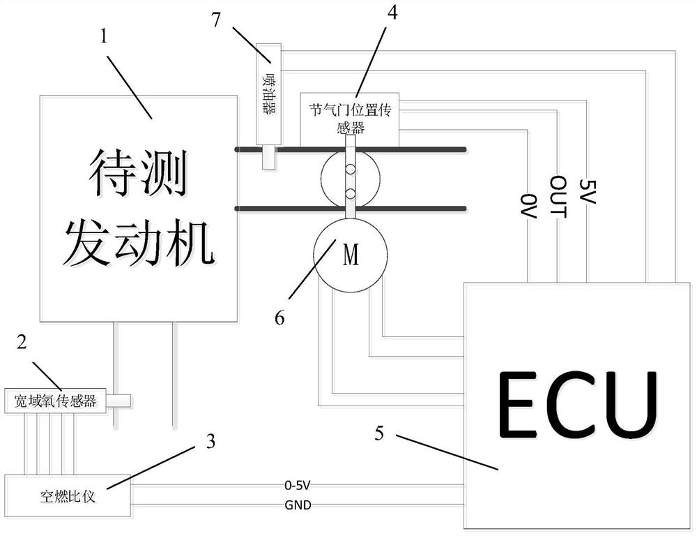
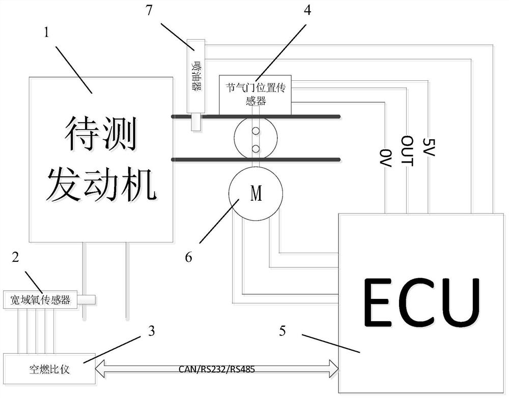
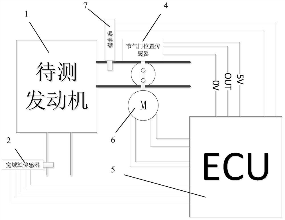
[0049] see figure 1 , figure 1It is a schematic diagram of the device structure of an embodiment of the present invention. Before the EFI system of the engine is put into mass production, various parameters of the engine need to be calibrated, including basic fuel injection pulse width, temperature correction, transient correction, plateau correction, etc. The electronic fuel injection system fuel automatic calibration device of the present invention is suitable for the basic fuel injection pulse width calibration of the engine electronic injection system, including: a dynamometer (not shown), the crankshaft output end of the engine to be tested 1 and the dynamometer The main function of the engine bench is to measure the power of the engine. There are two ways to measure the power of the AC dynamometer, one is constant spee...


PUM


Abstract

The invention provides an automatic fuel calibration device and method for an electric injection system and the automatic fuel calibration device and method are suitable for the basic oil injection pulse width calibration of the engine electric injection system. The device comprises a dynamometer, a wide-area oxygen sensor, an air-fuel ratio instrument, a throttle position sensor and a controller.An engine rack of the dynamometer is connected with the output end of a crankshaft of an engine to be tested. The wide-area oxygen sensor is mounted on an exhaust pipe of the engine to be tested andused for detecting the tail gas oxygen content of the engine to be tested. The air-fuel ratio instrument is connected with the wide-area oxygen sensor and used for obtaining the tail gas oxygen content by detecting a signal of the wide-area oxygen sensor and converting the tail gas oxygen content into the air-fuel ratio or the excess air coefficient. The throttle position sensor is mounted on a shaft of a throttle valve plate of the engine to be tested, and the voltage output by the throttle position sensor corresponds to the opening and closing angle of the throttle valve plate. The controller is connected with the air-fuel ratio instrument, the throttle position sensor and the engine rack and is used for calibrating the basic fuel injection pulse width. The invention further provides theautomatic fuel calibration method for the electric injection system by using the device.

Description

technical field [0001] The invention relates to a fuel calibration technology for an engine electronic injection system, in particular to an automatic fuel calibration device and method for an electronic fuel injection system. Background technique [0002] In the past, the method of calibrating the basic fuel injection pulse width table was manual operation, visually observing the air-fuel ratio meter, and manually modifying it. Calibration steps are as follows: [0003] 1. Adjust to the constant speed mode, manually set the speed one by one as the value on the axis of the basic fuel injection pulse width table; [0004] 2. Constantly at a certain speed, manually set the TPS opening degree to the value on the axis of the basic fuel injection pulse width table, or set the intake pressure; [0005] 3. Manually modify the basic fuel injection pulse width table, adjust the current fuel injection pulse width, and observe the readings of the air-fuel ratio meter, so that the cur...

Claims


Application Information

Patent Timeline
Patent Type & Authority Applications(China)
IPC IPC(8): F02M65/00
CPCF02M65/00
Inventor 梁世进陈健伟王康康
Owner HUAYI MECHANICAL & ELECTRICAL CO LTD
Learn More