Multi-satellite receiving clamp, receiver and receiving method

A jig and clip technology, which is applied to the structural connection of the antenna grounding switch, the antenna support/installation device, electrical components, etc., can solve the problem that the optimal receiving position of the satellite signal cannot be found, the structure of the parts and the production process are complicated, and it is unfavorable for large quantities. Production and application problems, to achieve the effect of improving debugging efficiency, low production cost, and fewer parts and components

Pending Publication Date: 2019-05-31
SICHUAN VIDEO ELECTRONICS
View PDF8 Cites 0 Cited by
  • Summary
  • Abstract
  • Description
  • Claims
  • Application Information

AI Technical Summary

Problems solved by technology

For the fixed type in the prior art, two or more feed sources that need to receive signals at the same time are cast into one body by die-casting technology. Although the structure is simple, the feed source on the sub-focus has no movement and There is no degree of freedom of rotation adjustment, so it is impossible to find the best receiving position for satellite signals, and it is also impossible to rotate and adjust the polarization angle of each feed source separately, so that when receiving linearly polarized satellite signals, the receiving efficiency will be reduced by 10% about
[0003] For the adjustable type in the prior art, in order to adopt the method of catheter welding, the catheters are respectively welded at the rotating movable joints, and the functions of movement and rotation can be realized in the three directions of the main focus feed source; although it can meet the multi-satellite Receive the requirement of focus adjustment advantages, but there are installation and debugging troubles, it is difficult to find the best focus, and the part structure and production process are complicated, the production cost is high, the efficiency is low, and it is very unfavorable for mass production and application.

Method used


Image

  • Multi-satellite receiving clamp, receiver and receiving method
  • Multi-satellite receiving clamp, receiver and receiving method
  • Multi-satellite receiving clamp, receiver and receiving method

Examples


Embodiment Construction

[0030] The following will clearly and completely describe the technical solutions in the embodiments of the present invention with reference to the drawings in the embodiments of the present invention. Obviously, the described embodiment is only one embodiment of the present invention, not all embodiments. Based on the embodiments of the present invention, all other embodiments obtained by persons of ordinary skill in the art without making creative efforts belong to the protection scope of the present invention.

[0031] In order to make the purpose, technical solution and advantages of the present application clearer, the present application will be further described in detail below in conjunction with the accompanying drawings and specific embodiments.

[0032] In the following description, references to "one embodiment," "an embodiment," "an example," "example," etc. indicate that such described embodiment or example may include a particular feature, structure, characterist...


PUM


Abstract

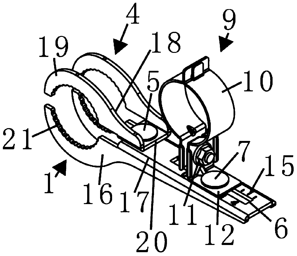
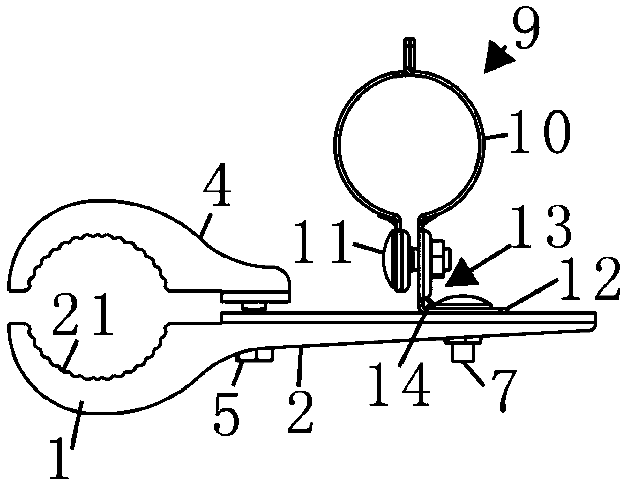
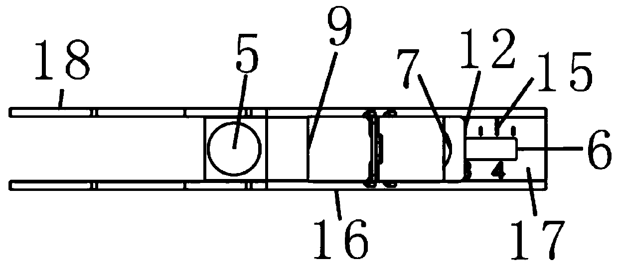
The invention discloses a multi-satellite receiving clamp, a receiver and a receiving method. The receiving clamp comprises a bracket seat provided with a curved arc structure at one end and a bracketcover matching the curved arc structure and used for clamping a main feed source, wherein the bracket seat is connected to a side of the bracket cover by a bolt a; a long hole is formed in the bracket seat; and at least one metal feed source clip for clamping an auxiliary feed source is connected to the long hole by a bolt b. The receiver includes a satellite antenna and the multi-satellite receiving clamp. A support back frame is mounted on one end of the satellite antenna. The multi-satellite receiving clamp is mounted on the support back frame through a feed source rod. The feed source rodis located on a side of the reflecting surface of the antenna. The free end of the feed source rod is connected to the curved arc structure of the bracket seat through a main focal feed source clip.The multi-satellite receiving clamp, the receiver and the receiving method are high in debugging precision, simple in design structure, convenient to machine, less in components, low in cost and suitable for mass production and application.

Description

technical field [0001] The invention relates to the field of signal reception, in particular to a multi-satellite receiving fixture, a receiver and a receiving method. Background technique [0002] At present, the multi-satellite receiving technical scheme mainly has two kinds of fixed type and adjustable type. For the fixed type in the prior art, two or more feed sources that need to receive signals at the same time are cast into one body by die-casting technology. Although the structure is simple, the feed source on the sub-focus has no movement and There is no degree of freedom of rotation adjustment, so it is impossible to find the best receiving position for satellite signals, and it is also impossible to rotate and adjust the polarization angle of each feed source separately, so that when receiving linearly polarized satellite signals, the receiving efficiency will be reduced by 10% about. [0003] For the adjustable type in the prior art, in order to adopt the metho...

Claims


Application Information

Patent Timeline
Patent Type & Authority Applications(China)
IPC IPC(8): H01Q1/12H01Q1/50H01Q19/12
CPCY02D30/70
Inventor 李顺根
Owner SICHUAN VIDEO ELECTRONICS
Why Eureka
Try Eureka