A distribution box with good heat dissipation performance for two-way linkage cranes

A heat dissipation performance, crane technology, applied in the direction of electrical components, substation/switch layout details, substation/switchgear cooling/ventilation, etc., can solve the problems of air pump inhaling a large amount of dust, difficult installation of electrical components, dustproof box and other problems , to increase the heat dissipation contact area, facilitate maintenance and cleaning, and ensure the effect of dustproof performance

Active Publication Date: 2020-07-10
WUHAN UNIV OF TECH
View PDF1 Cites 0 Cited by
  • Summary
  • Abstract
  • Description
  • Claims
  • Application Information

AI Technical Summary

Problems solved by technology

[0004] The heat dissipation distribution box device in the above patent has the following disadvantages: the box is full of ventilation pipes, the electrical components are not easy to install, and the cooling is done by air cooling, the air pump will suck a lot of dust, the dustproof problem inside the box is serious, and a large number of small air outlets are opened , easily cause blockage

Method used


Image

  • A distribution box with good heat dissipation performance for two-way linkage cranes
  • A distribution box with good heat dissipation performance for two-way linkage cranes
  • A distribution box with good heat dissipation performance for two-way linkage cranes

Examples


Embodiment 1

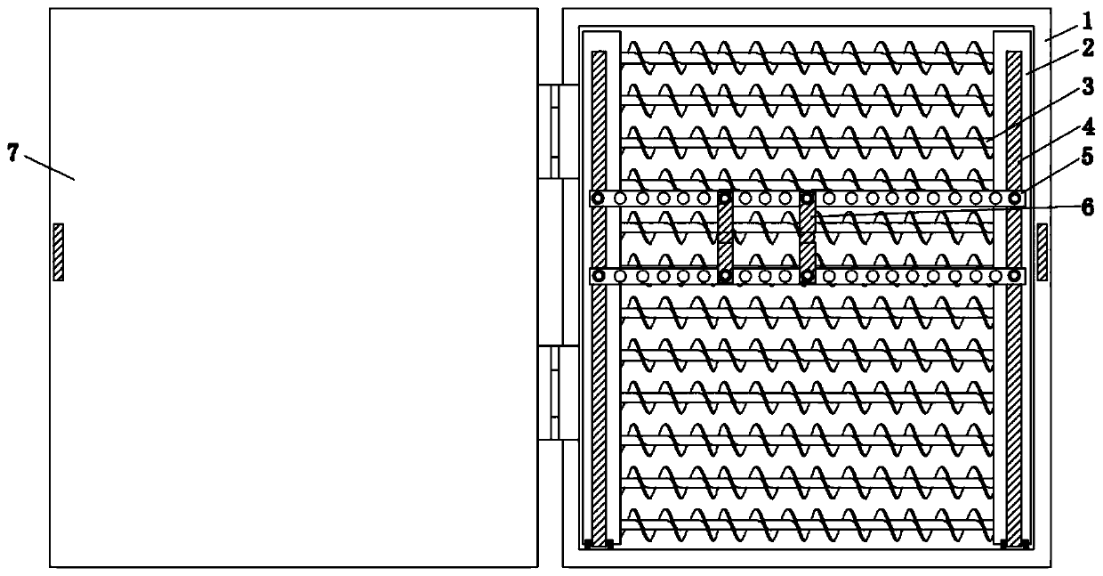
[0027] Such as Figure 1-2 As shown, it includes a box body 1, and vertically arranged inner flow pipes 2 are fixed on the left and right sides of the inner wall of the backboard of the box body 1, and a number of equidistantly distributed inner flow pipes 2 are provided on the side walls opposite to each other. The first installation hole, the two first installation holes where the internal flow pipes 2 on both sides are located on the same horizontal line are all screw-connected with the same heat-absorbing pipe 3, and are fixed on both sides of the outer wall of the backboard of the box body 1 with the inner Outflow tubes 12 arranged horizontally, and the side walls of the two outflow tubes 12 opposite to each other are provided with a number of equidistantly distributed second installation holes, and the outflow tubes 12 on both sides are located on the two second mounting holes on the same horizontal line. The installation holes are all screwed with the same cooling pipe ...

Embodiment 2

[0031] Embodiment 2 is a technical solution further optimized on the basis of Embodiment 1. Embodiment 2 is based on Embodiment 1. The bottom of the inner wall of the box body 1 is hinged with a pillar 4 arranged parallel to the inner flow pipe.

[0032] Such as Figure 5 As shown, the two inner flow pipes 2 and the two pillars 4 are connected by electric telescopic rods 14, and the two ends of the two electric telescopic rods 14 are respectively arranged opposite to the inner flow pipes 2 and the outer walls of the pillars 4. Hinged, the telescopic length of the electric telescopic rod 14 controls the distance between the pillar 4 and the inner flow pipe 2 .

[0033] Such as Figure 4 As shown, there are two horizontally arranged beam frames 5 slidingly connected between the two pillars 4, and several installation holes 17 are equidistantly distributed on the beam frames 5, and the vertical beam frames 6 are fixed between the two beam frames 5 by bolts. Install vertically w...


PUM


Abstract

The invention discloses a distribution box with good heat dissipation performance for a two-way linkage crane. The distribution box comprises a box body. Vertical internal flow tubes are fixed to theleft and right sides of the inner wall of a box backplane. The two first mounting holes of the internal flow tubes on both sides in the same horizontal line are in threaded connection to the same heatabsorbing tube. External flow tubes are fixed to the both sides of the outer wall of box backplane and are horizontal with the internal flow tubes. The two second mounting holes of the external flowtubes on both sides in the same horizontal line are in threaded connection to the same heat dissipating tube. The internal flow tubes and the external flow tubes communicate with each other through aninteractive pipe. The interactive pipe is provided with an oil pump. The interactive pipe and the oil pump form a circulating convection between the internal flow tubes and the external flow tubes. The distribution box, while using oil cooling technology for cooling, ensures the dustproof performance of the box body. The internal oil cooling pipeline can achieve maximum installation and improve heat dissipation efficiency. The number and the sizes of electrical component mounting parts can be adjusted, which is convenient and practical.

Description

technical field [0001] The invention relates to the technical field of crane distribution boxes, in particular to a distribution box for bidirectional linkage cranes with good heat dissipation performance. Background technique [0002] The distribution box is the control center that directs the various components in the power supply line to distribute power reasonably. It is the control link that reliably receives the upper-end power supply and correctly feeds out the load power. It is also the key to obtaining whether the user is satisfied with the power supply quality. [0003] The Chinese patent authorization number is CN206349649U, which discloses a heat dissipation distribution box, which includes a box body, and the box body is respectively provided with an air box one and an air box two on the opposite side walls, the first air box and the second air box The top is respectively provided with an air inlet pipe and an air outlet pipe protruding from the top of the box b...

Claims


Application Information

Patent Timeline
Patent Type & Authority Patents(China)
IPC IPC(8): H02B1/56H02B1/48
Inventor 王小虎周勇
Owner WUHAN UNIV OF TECH
Why Eureka
Try Eureka