
A debugging device capable of accurately adjusting and correcting through infrared operation for a binocular camera

A binocular camera and infrared technology, which is applied in the field of ADAS, can solve the problems of wasting the time of operators and installation personnel, the external structure design is not ideal, and the installation and adjustment are not convenient enough.

Inactive Publication Date: 2019-05-31
深圳市华芯技研科技有限公司
View PDF0 Cites 2 Cited by
  • Summary
  • Abstract
  • Description
  • Claims
  • Application Information

AI Technical Summary

Problems solved by technology

[0004] The object of the present invention is to provide a debugging device for binocular camera that can be accurately adjusted and corrected by infrared operation, so as to solve the problem that the external structure design of the main body is not ideal when the existing debugging device proposed in the above background technology is used, such as The main body is not designed with a flexible installation and adjustment mechanism, which leads to the inconvenient installation and adjustment of the main body, which causes unnecessary troubles for users and wastes the time of operating and installing personnel

Method used


Image

  • A debugging device capable of accurately adjusting and correcting through infrared operation for a binocular camera
  • A debugging device capable of accurately adjusting and correcting through infrared operation for a binocular camera
  • A debugging device capable of accurately adjusting and correcting through infrared operation for a binocular camera

Examples


example 1

[0029] After the system is started, the initialization unit of the FPGA will initially set the camera, and the adjustment and correction parameter table will be transmitted from the external PC to the internal SRAM. Afterwards, the pictures captured simultaneously by the stereo camera will be input to the IF interface module through the stereo camera, and after initial processing and synchronization of the left and right pictures, it will be stored in the internal SRAM memory of the adjustment and correction module of the left and right cameras. The images read by the internal SRAM are used in the left and right camera adjustment module to perform tilt correction and camera position correction by referring to the initial parameter table stored in other internal SRAMs, and store them in the internal SRASM of the stereo matching module. Afterwards, the picture data can be read out from the internal stereo matching unit and the weak mode elimination unit at any time, and carry out...

example 2

[0035] Since the matching is carried out in two-dimensional mode, in order to be able to process correctly, feature regions with edge enhancement are required in both directions. First, use formula 1 to obtain the brightness gradient on the pixels connected to the difference filter The strength and direction of:

[0036]

[0037]

[0038] The same process is performed on the feature area of ​​4×4 pixels, and the histogram of each direction is obtained. Quantization is performed in 8 directions, and if the intensity does not exceed the threshold, no voting is performed. If there are no two directions of 180 degrees and its frequency exceeds the threshold, its characteristic area is regarded as a singularity;

[0039] The two-dimensional matching process adopts the regional reference method. The size of the search area is 512×8 pixels, and the window size for detecting singularities is 4×4 pixels. In addition, SADSum of Absolute Difference is used in the evaluation func...

example 3

[0044] The various processing methods described above realize small scale and high speed by parallelization and pipeline in units of 4 lines. And it can be realized under the premise of only relying on the internal memory SRAM of the FPGA without using an external memory. Table 1 shows the FPGA resources of the stereo camera system including this real-time auto-correction:

[0045]

[0046]

[0047] In order to investigate whether the processing is appropriate, the comparison image is rotated by 0.97mrad, so that it is offset by 1.5 pixels in the vertical direction for testing. The center of rotation is the image center. After that, automatic correction processing is performed. After 1 minute from the start of processing, the slope can be found to be 0.73mrad, and the vertical offset is 1.5 pixels, and then trimmed;

[0048] In addition, for one automatic correction process, when the threshold of the number of singular points detected in one large module is set to 50%...


PUM


Abstract

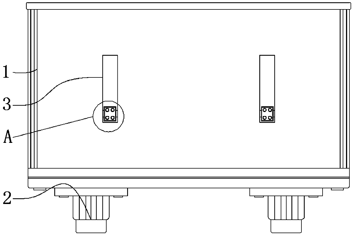
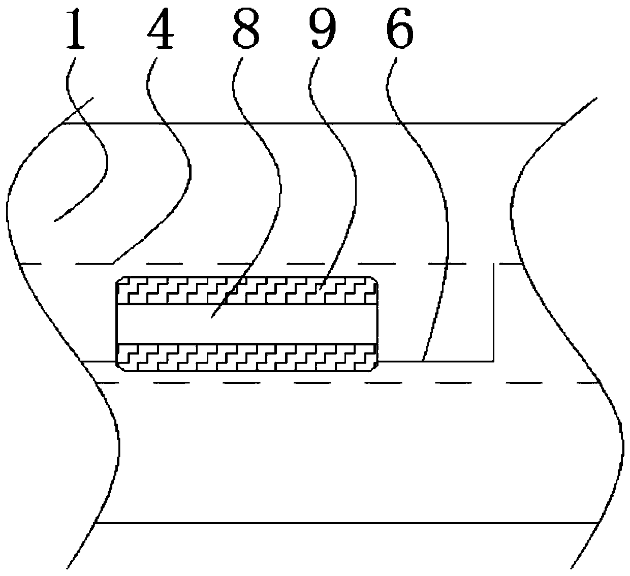
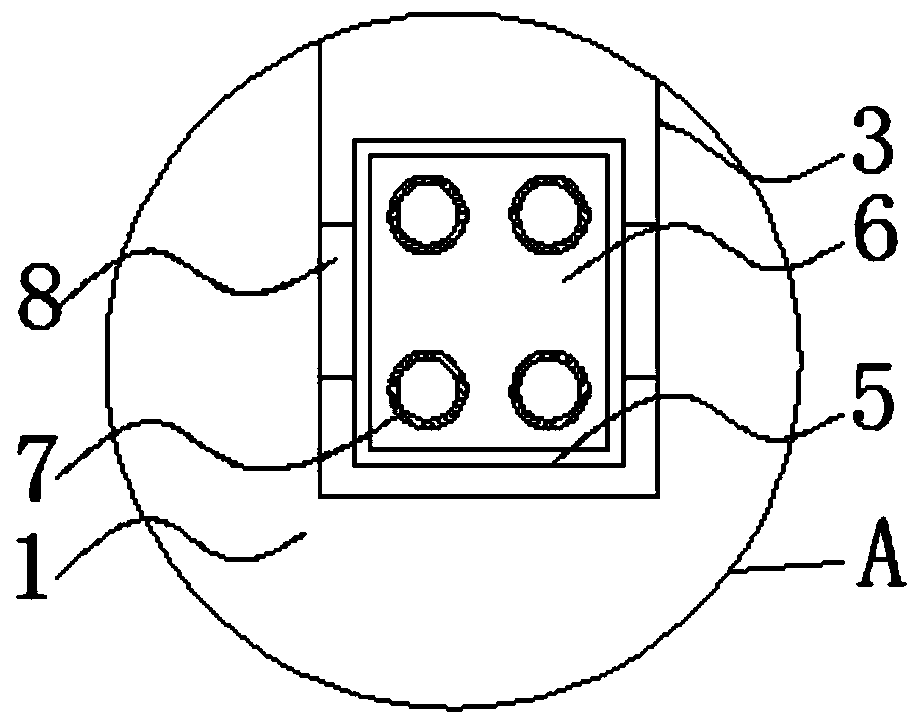
The invention relates to a debugging device capable of accurately adjusting and correcting through infrared operation for a binocular camera. The device comprises a device body and a fixing mechanism,lenses are installed on the left side and the right side of the front end of the device body, a connecting penetrating channel is formed in the outer wall of the upper end of the device body, the bottom end of the connecting penetrating channel is connected with an inner end connecting channel, and the inner end of the connecting penetrating channel is connected with the fixing mechanism. The beneficial effects of the invention are as follows: the paint has good effects; according to the infrared operation debugging device for the binocular camera, the correction debugging device can be accurately adjusted; a clamping device and connection inverted teeth are arranged; the engagement inverted teeth designed at the upper end of the position clamping device can be attached to the upper wallof the inner end connecting channel in a staggered mode; and the positioning device can be attached to the bottom end of the inner end connecting channel through the connection inverted teeth at the bottom end of the clamping device, so that friction force is generated between the connection inverted teeth and the bottom end of the inner end connecting channel, sliding adjustment of the clamping device is further made to be slower, and the safety performance of the clamping device in the using process is improved.

Description

technical field [0001] The invention relates to the technical field of ADAS, in particular to a debugging device for a binocular camera that can be precisely adjusted and corrected by infrared operation. Background technique [0002] Advanced Driving Assistant System (Advanced Driving Assistant System) uses various sensors installed on the car to sense the surrounding environment at any time during the driving process of the car, collect data, and carry out identification, detection and tracking of static and dynamic objects , combined with the map data of the navigator, to carry out systematic calculation and analysis, so that the driver can be aware of possible dangers in advance, and effectively increase the comfort and safety of driving. [0003] When the existing debugging device is used, the outer structure design of the main body is not ideal. If the small mechanism for flexible installation and adjustment is not designed for the main body, the installation and adjust...

Claims


Application Information

Patent Timeline
Patent Type & Authority Applications(China)
IPC IPC(8): H04N5/225
Inventor 姜珂
Owner 深圳市华芯技研科技有限公司
Learn More