The invention discloses intelligent traffic monitoring equipment capable of rotating by 360 degrees

A technology of intelligent transportation and monitoring equipment, applied in the direction of mechanical equipment, use feedback control, image communication, etc., can solve the problems of small monitoring range, inability to effectively rotate, and low intelligent level of road monitoring, and achieve high intelligent level Effect

Inactive Publication Date: 2019-05-31
广东赛达交通科技股份有限公司
View PDF7 Cites 4 Cited by
  • Summary
  • Abstract
  • Description
  • Claims
  • Application Information

AI Technical Summary

Problems solved by technology

[0003] However, the existing road monitoring has a low degree of intelligence and cannot be effectively rotated, resulting in a small monitoring range. Therefore, a 360°rotating intelligent traffic monitoring device is proposed to solve the above problems

Method used


Image

  • The invention discloses intelligent traffic monitoring equipment capable of rotating by 360 degrees
  • The invention discloses intelligent traffic monitoring equipment capable of rotating by 360 degrees
  • The invention discloses intelligent traffic monitoring equipment capable of rotating by 360 degrees

Examples


Embodiment 1

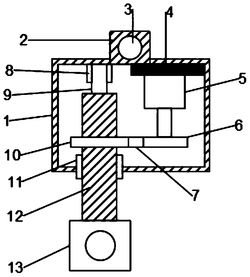
[0022] see figure 1 , in an embodiment of the present invention, a 360° rotating intelligent traffic monitoring device includes a housing 1, a connecting cylinder 2, a conveyor belt 7, a second connecting rod 12 and a camera 13, and a fixed connection is arranged in the middle of the top of the housing 1 The connection cylinder 2 is provided with a connection hole 3 on the connection cylinder 2, and the device is fixed through the connection cylinder 2 and the connection hole 3. The right end of the top inner surface of the housing 1 is provided with a fixedly connected buffer plate 4 , the buffer plate 4 is fixedly connected with the upper end of the first motor 5, plays the role of buffering and protecting the first motor 5 through the buffer plate 4, and prolongs the service life of the first motor 5; meanwhile, the lower end of the output shaft of the first motor 5 is provided with The fixedly connected driving wheel 6, the driving wheel 6 is connected with the driven whee...

Embodiment 2

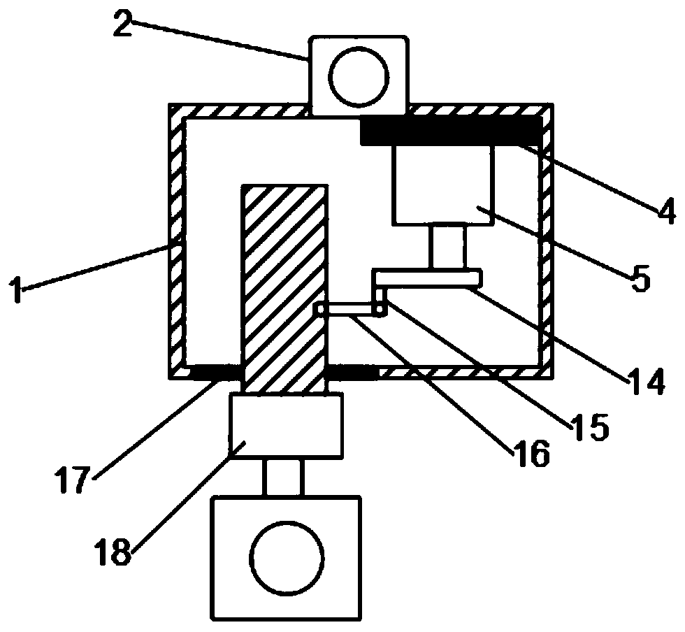
[0026] see figure 2 , The difference between embodiment 2 and embodiment 1 is that the driving wheel 6, the conveyor belt 7, the first bearing 8, the first connecting rod 9, the driven wheel 10 and the second bearing 11 are replaced by the first cam 14, the first hinge rod 15. The second articulated rod 16, the elastic rubber 17 and the second motor 18, the lower end of the output shaft of the first motor 5 is provided with a fixedly connected first cam 14, and the long and short bottom of the first cam 14 is provided with a fixedly connected The first articulated rod 15, the lower end of the first articulated rod 15 is hinged with the right end of the second articulated rod 16, the left end of the second articulated rod 16 is articulated with the second connecting rod 12, and the second connecting rod 12 Through the shell 1, it is fixedly connected with the elastic rubber 17, and the elastic rubber 17 is fixedly connected with the bottom of the shell 1. The elastic rubber 17...

Embodiment 3

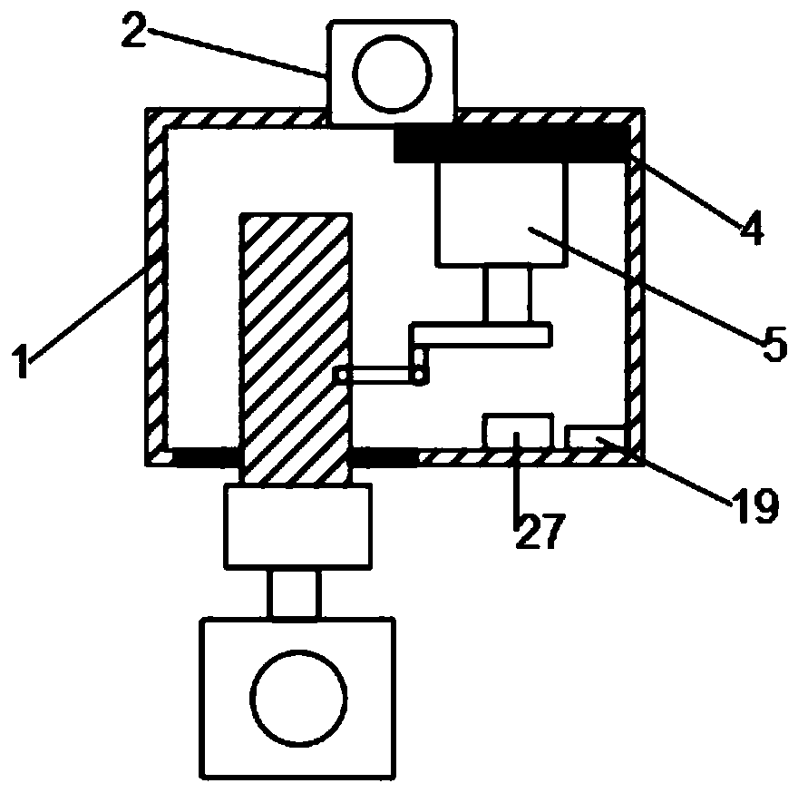
[0029] see image 3 The difference between embodiment 3 and embodiment 1 or embodiment 2 is that it also includes a sound localization device 19 and a controller 27. On the left side of the device 19, when the detection is performed, there is an abnormal sound, the position is determined at the first time and a signal is sent to the camera 13, and the camera 13 sends the signal to the elastic rubber 17, and the controller 27 controls the first motor 5 and the second The motor 18 rotates to adjust the position of the camera 13, thereby realizing intelligent monitoring.


PUM


Abstract

The invention discloses an intelligent traffic monitoring device capable of rotating by 360 degrees. Relating to the field of intelligent transportation, The problem that an existing monitoring deviceis small in monitoring range is mainly solved. Including a housing, Connecting column, the conveying belt, a second connecting rod and a camera are arranged; a fixedly connected connecting column body is arranged in the middle of the top of the shell; a connecting hole is formed in the connecting column body; A buffer plate fixedly connected is arranged at the right end of the inner surface of the top of the shell. the buffer plate is fixedly connected with the upper end of a first motor; a fixedly connected driving wheel is arranged at the lower end of an output shaft of the first motor; andthe driving wheel is connected with a driven wheel through a conveying belt, the driven wheel is fixedly arranged on a second connecting rod, and a detachably connected camera is arranged at the lower end of the second connecting rod. The intelligent monitoring device can rotate by 360 degrees for monitoring, is high in intelligent degree, can automatically adjust the monitoring position, and issuitable for popularization.

Description

technical field [0001] The invention relates to the field of intelligent traffic, in particular to a 360° rotating intelligent traffic monitoring device. Background technique [0002] Road monitoring is mainly based on speed ball monitoring. The monitoring points are distributed at road intersections and key road sections where the traffic flow and pedestrian flow are relatively concentrated. The road surface conditions in each area are adjusted to adjust the vehicle flow at each intersection to ensure smooth traffic. It can detect and arrange to deal with road traffic accidents in a timely manner for monitoring violations of road vehicles, and can provide technical support for the detection of various cases such as traffic and public security, greatly improving the level and efficiency of public security organs in law enforcement and case handling. [0003] However, the existing road monitoring has a low degree of intelligence and cannot be effectively rotated, resulting i...

Claims


Application Information

Patent Timeline
Patent Type & Authority Applications(China)
IPC IPC(8): H04N7/18H04N5/232G05D3/12F16M11/08F16M11/18F16M13/02G01S15/06
Inventor 李旭辉黄奕辉
Owner 广东赛达交通科技股份有限公司
Why Eureka
Try Eureka