[0042] In order to make the purpose, technical solutions and advantages of the embodiments of the present application clearer, the technical solutions in the embodiments of the present application will be clearly and completely described below in conjunction with the drawings in the embodiments of the present application. It should be understood that the appended The figures are only for the purpose of illustration and description, and are not used to limit the protection scope of the present application. Additionally, it should be understood that the schematic drawings are not drawn to scale. The flowcharts used in this application illustrate operations implemented in accordance with some embodiments of the application. It should be understood that the operations of the flowcharts may be performed out of order, and steps that have no logical context may be performed in reverse order or concurrently. In addition, those skilled in the art may add one or more other operations to the flowchart or remove one or more operations from the flowchart under the guidance of the content of the present application.
[0043] In addition, the described embodiments are only some of the embodiments of the application, not all of the embodiments. The components of the embodiments of the application generally described and illustrated in the figures herein may be arranged and designed in a variety of different configurations. Accordingly, the following detailed description of the embodiments of the application provided in the accompanying drawings is not intended to limit the scope of the claimed application, but merely represents selected embodiments of the application. Based on the embodiments of the present application, all other embodiments obtained by those skilled in the art without making creative efforts belong to the scope of protection of the present application.
[0044] It should be noted that the term "comprising" will be used in the embodiments of the present application to indicate the existence of the features stated later, but does not exclude the addition of other features.
[0045] It should be noted that like numerals and letters denote similar items in the following figures, therefore, once an item is defined in one figure, it does not require further definition and explanation in subsequent figures.
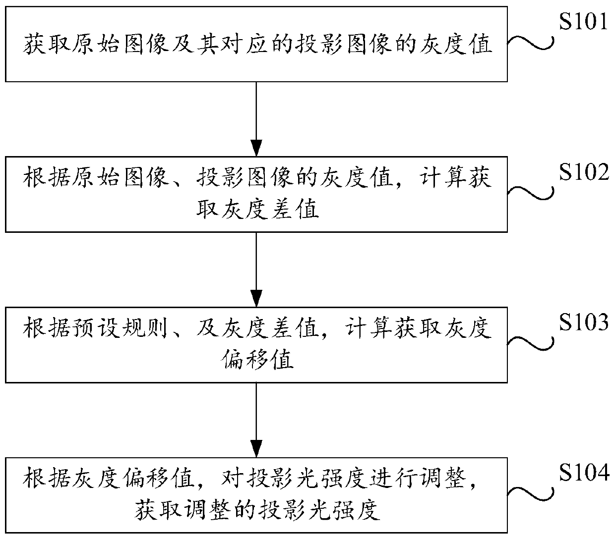
[0046] Please refer to figure 1 , figure 1 Schematic diagram of the projection light color adjustment method provided in the embodiment of this application Figure 1 , the execution subject of this embodiment may be a projector, a computer, a server, a processing device with a data processing function, and the like. The projection light color adjustment method includes:
[0047] S101. Acquire grayscale values of the original image and its corresponding projected image.
[0048] Optionally, the original image may include multimedia image information such as pictures, audio and video, audio and video, or surveillance video. In this embodiment, the projector may project the original image, and then acquire the projection image corresponding to the original image, and acquire the gray value of the original image and the corresponding projection image.
[0049] It should be noted that in the RGB model, if R=G=B, the color represents a grayscale color, and the value of R=G=B is called the grayscale value. Usually the original image and projected image obtained above are all color images, each pixel of which is composed of three basic pigments R (red), G (green), and B (blue), and the colors of R, G, and B The value is between [0, 255]. Calculating directly using color images has a relatively large amount of calculation, and it is not necessarily necessary to process all three components of R, G, and B. Grayscale processing is performed on the original image and its projected image to obtain the corresponding grayscale value of the original image and the grayscale value of the projected image, which can reduce the amount of calculation in the subsequent calculation process and improve the processing efficiency to a certain extent.
[0050]Optionally, the maximum value method can be used to perform grayscale processing on the original image and its corresponding projected image, for example: take the maximum value among the three values of R, G, and B as the grayscale value, Gray=max{R, G , B}; then the value of the pixel (R, G, B) after grayscale processing is (Gray, Gray, Gray), and the grayscale value of the image is Gray; the average value method can also be used for calculation, for example: take R , G, B as the gray value of the pixel, Gray=(R+G+B)/3, then the gray value of the pixel (R, G, B) is (Gray, Gray, Gray), the grayscale value of the image is Gray; in addition, the grayscale processing of the image can also use weighted average method, component method, etc. In this embodiment, there is no specific limitation on the calculation method of the gray value, which can be selected according to actual requirements.
[0051] S102. Calculate and obtain a grayscale difference according to the grayscale values of the original image and the projected image.
[0052] It should be noted that different gray values in the projected image reflect different reflections of the image to be projected in the projected domain. Wherein, the projection domain is the target area on which the image to be projected is projected. For example: when a movie needs to be projected through a projector, the corresponding projection area can be a wall, etc.; another example: when the image to be projected is projected into the car, the corresponding projection area can be a center console, etc.
[0053] Optionally, after the grayscale values of the original image and the projected image are acquired through the above calculation, the difference between the grayscale value of the original image and the grayscale value of the projected image, that is, the grayscale difference, may be calculated. Due to the difference in surface material and color at different positions in the projection domain, the gray value of each part of the projected image is different from the gray value of the original image, that is, the overall gray value of the projected image is different from the overall gray value of the original image. There is a difference between the values, so the difference between the gray value of the original image and the projected image can be calculated.
[0054] S103. Calculate and acquire a grayscale offset value according to a preset rule and the grayscale difference.
[0055] It should be noted that in the same projection area, different projection positions have differences in the brightness and darkness of the projected image. For example, the projected image at position A is brighter than the original image, and the projected image at position B is darker than the original image. Compared with the gray value of the original image, the gray value of the projected image may be larger or smaller.
[0056] Optionally, the grayscale offset value may be calculated according to the grayscale difference between the original image and the projected image obtained above, and a preset rule. Specifically, for different gray scale differences, there are differences in the calculation methods of corresponding gray scale offset values, and specific calculations may be performed according to actual gray scale difference values.
[0057] S104. Adjust the projection light intensity according to the gray scale offset value, and obtain the adjusted projection light intensity.
[0058] Optionally, after the above calculation obtains the grayscale offset value, the original projected light intensity may be adjusted to the grayscale offset value and re-projected. Wherein, the original projected light intensity is the corresponding light intensity when the projected projected image is abnormal (the projected image is dark, blurred, etc.). For example, if the original projection light intensity is 100, and the grayscale offset value obtained by the above calculation is 150, then the adjusted projection light intensity is 150, that is, the original projection light intensity is discarded, and the calculated grayscale offset value is used as The adjusted projection light intensity is used to re-project the original image to obtain an ideal projection image.
[0059] The projection light color adjustment method provided in the embodiment of the present application obtains the projection image corresponding to the original image, calculates the gray value of the original image and the projection image, and calculates the gray value difference, according to the preset rules and the obtained gray value The difference is to calculate the grayscale offset value, and use the grayscale offset value to adjust the projection light intensity to obtain the adjusted projection light intensity, and re-project to obtain a clear and uniform projection image. The calculation process of this method is simple, and the practicability is good, which effectively solves the problem of poor vehicle projection effect.
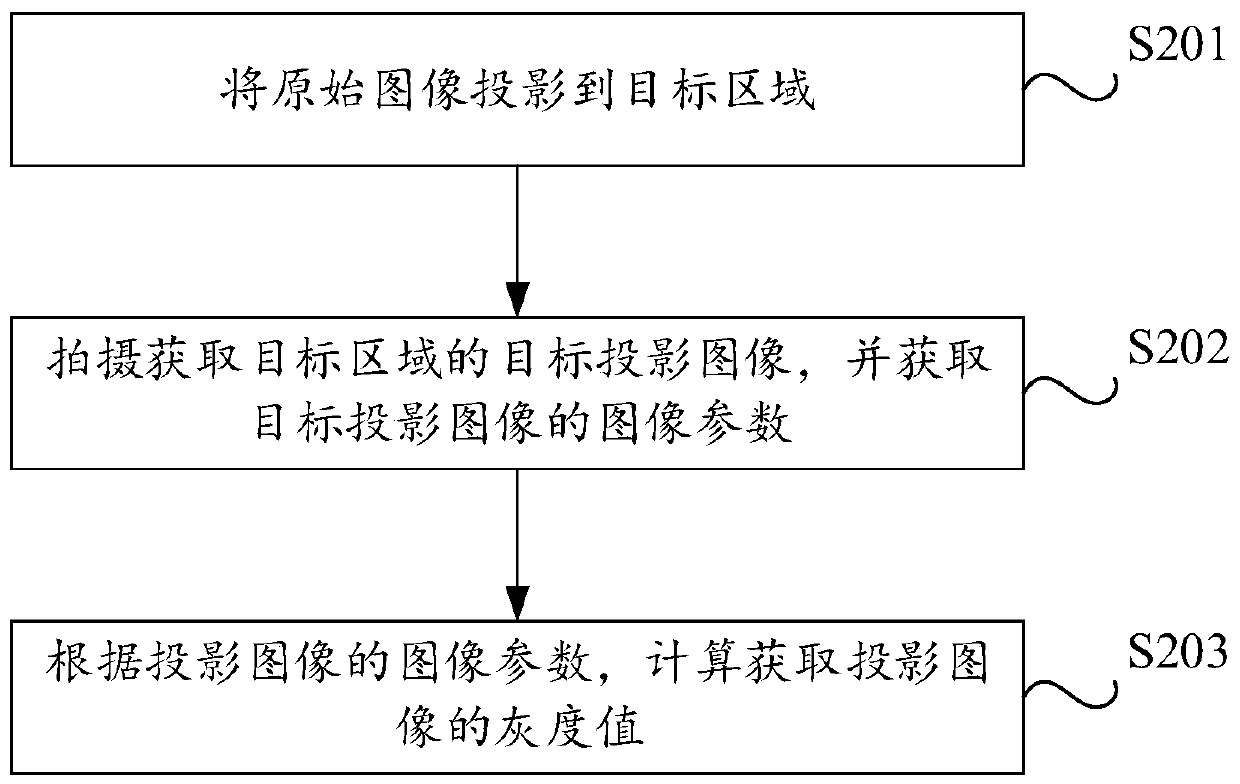
[0060] figure 2 Schematic diagram of the projection light color adjustment method provided in the embodiment of this application Figure II , further, before obtaining the gray value of the original image and its corresponding projected image, it also includes:
[0061] S201. Project the original image to the target area.
[0062] Optionally, the original image may be sent to a projector, and the projector receives the original image and projects it to a preset target projection area. Wherein, in this embodiment, the preset target projection area may be the interior of the vehicle, such as the center console. Optionally, the target projection area may also be a wall, a blackboard, or a projection screen.
[0063] S202. Capture and acquire a target projection image of the target area, and acquire image parameters of the target projection image.
[0064] Optionally, the camera in the projector may be used to capture the projected image and obtain image parameters of the projected image, wherein the image parameters may include: R/G/B color channel components of the image, color saturation parameters, brightness parameters etc.
[0065] S203. According to the image parameters of the projected image, calculate and acquire the gray value of the projected image.
[0066] Specifically, the gray value of the projected image is calculated and obtained according to the projected image parameters obtained above. The specific calculation process has been given in the above embodiments, and will not be repeated here.
[0067] image 3 Schematic diagram of the projection light color adjustment method provided in the embodiment of this application Figure three , further, according to the preset rules and the grayscale difference, calculate and obtain the grayscale offset value, including:
[0068] S301. Calculate the sum of the grayscale difference and a preset compensation value according to the grayscale difference.
[0069] Optionally, the preset compensation value can be stored in the processor of the projector in advance. After the projector acquires the original image and the projected image, the gray value of the original image and the projected image can be obtained by calculating the gray value of the original image and the projected image by the projector. Grayscale difference.
[0070] It should be noted that adding the calculated grayscale difference to the compensation value can make the light intensity loss of the projected image corresponding to the original image smaller. For example, the grayscale value of the original image is 150, and the grayscale value of the corresponding projected image The intensity value is 20, that is, after the original image is projected, the light loss of the projected image obtained is relatively large, so the gray value is small. Adding the compensation value to it can make up for the light loss properly, thereby improving the projection quality. The shadow effect of the image.
[0071] S302. Obtain a grayscale offset value according to the sum of the grayscale difference and the preset compensation value.
[0072] Optionally, the sum of the calculated grayscale difference and the preset compensation value can be used as a grayscale offset value, and the projection light intensity can be adjusted by using the grayscale offset value, which can effectively improve the projection effect.
[0073] Optionally, assuming that the preset compensation value is 100, the calculated grayscale value of the original image is 150, and the grayscale value of the corresponding projected image is 130, the grayscale difference value is 20, and the grayscale difference value is the same as the preset The sum of compensation values is 20 plus 100, that is, the grayscale offset value is 120; and when the grayscale value of the original image is 150, the grayscale value of the corresponding projected image is 20, and the grayscale difference value is 130 , the sum of the grayscale difference and the preset compensation value is 130 plus 100, that is, the grayscale offset value is 230. It should be noted that when the above-mentioned grayscale difference is larger, it means that the light intensity of the projected image corresponding to the original image is weaker, and after adding a compensation value to it, the grayscale offset value is obtained, and the grayscale offset value is used to To adjust the projection light intensity, the projection light intensity is greatly improved, thereby improving the projection effect. Correspondingly, when the grayscale difference is small, it indicates that the light intensity loss of the projection image corresponding to the original image is less, and the compensation value is added to it , get the grayscale offset value, use the grayscale offset value to adjust the projection light intensity, the resulting projected image will have a smaller gap with the original image, even if there will be a small light loss, but it will not affect the projection Effect.
[0074] Further, the projected image is an image projected inside the vehicle.
[0075] It should be noted that the method provided by this application can be applied in the car. Because the structure in the car is irregular in shape, image distortion is more likely to occur during projection. This method can effectively solve the problem of poor projection effect when projecting in the car. The problem.
[0076] Optionally, this method is not limited to being applied to in-vehicle projection. In the process of projection, this method can be used to adjust the light color to improve the projection effect.
[0077] Further, the preset compensation value is 120.
[0078] Optionally, the aforementioned preset compensation value is set to 120. By adding the preset compensation value to the gray scale difference as the adjusted projection light intensity, when the adjusted projection light intensity is used for projection, the gray value of the projected area obtained is relatively uniform, so that the gray scale of the projected image obtained The values are also relatively uniform.
[0079] It should be noted that the preset compensation value is obtained by researchers in related fields through multiple experiments. When the preset compensation value is 120, the corresponding calculation result is relatively accurate. Correspondingly, the projection light intensity is calculated using the calculation result. Adjustment, using the adjusted projection light intensity to re-project the original image, the obtained projection image has a better effect and improves the viewing experience of the viewer.
[0080] Figure 4 The schematic diagram of the gray value distribution in the projected domain provided for the embodiment of this application, as shown in Figure 4 As shown, the image includes a variety of colors in different shades. The darker the color, the smaller the gray value, and the lighter the color, the larger the gray value. When the original image is projected to such an area, some parts of the projected image will be very dark, some parts will be very bright, some parts will be clear, and some parts will be blurred, which will cause the original image to be projected out and be distorted, and the projection effect will be poor , affecting the viewing experience of the viewer.
[0081] Figure 5 The schematic diagram of the adjusted gray value distribution in the projected domain provided for the embodiment of this application shows that after adjusting the projected light color using the improved method of this application, and then re-projecting, the gray value of the projected domain obtained is relatively uniform, so that After the image is projected onto it, the light and color distribution of the obtained projected image is also relatively uniform, and the projection effect is significantly improved.
[0082] The projection light color adjustment method provided in the embodiment of the present application obtains the projection image corresponding to the original image, calculates the gray value of the original image and the projection image, and calculates the gray value difference, according to the preset rules and the obtained gray value The difference is to calculate the grayscale offset value, and use the grayscale offset value to adjust the projection light intensity to obtain the adjusted projection light intensity, and re-project to obtain a clear and uniform projection image. The calculation process of this method is simple, and the practicability is good, which effectively solves the problem of poor vehicle projection effect.
[0083] Image 6 A schematic structural diagram of a projection light color adjustment device provided for an embodiment of the present application, as shown in Image 6 As shown, the device includes: an acquisition module 401 , a calculation module 402 and a determination module 403 .
[0084] The obtaining module 401 is used to obtain the gray value of the original image and its corresponding projection image; the calculation module 402 is used to calculate and obtain the gray value difference according to the gray value of the original image and the projected image; according to preset rules, and The grayscale difference value is calculated to obtain a grayscale offset value; the determining module 403 is configured to adjust the projection light intensity according to the grayscale offset value, and obtain the adjusted projection light intensity.
[0085] Further, as Figure 7As shown, it also includes: a projection module 404; the projection module 404 is used to project the original image to the target area; the acquisition module 401 is also used to shoot and obtain the target projection image of the target area, and obtain the image parameters of the target projection image; The image parameters of the projected image are calculated to obtain the gray value of the projected image.
[0086] Further, the calculation module 402 is also used to calculate the sum of the grayscale difference and the preset compensation value according to the grayscale difference; obtain the grayscale offset value according to the sum of the grayscale difference and the preset compensation value .
[0087] Further, the projected image is an image projected inside the vehicle.
[0088] Further, the preset compensation value is 120.
[0089] Figure 8 A schematic structural diagram of a projection light color adjustment device provided in another embodiment of the present application, as shown in Figure 8 As shown, the device includes: a processor 501 and a memory 502, wherein: the memory 502 is used to store programs, and the processor 501 invokes the programs stored in the memory 502 to execute the foregoing method embodiments. The specific implementation manner and technical effect are similar, and will not be repeated here.
[0090] The device may be integrated into equipment such as a terminal or a server, which is not limited in this application.
[0091] Optionally, the present invention further provides a program product, such as a computer-readable storage medium, including a program, and the program is used to execute the foregoing method embodiments when executed by a processor.
[0092] Those skilled in the art can clearly understand that for the convenience and brevity of the description, the specific working process of the system and device described above can refer to the corresponding process in the method embodiment, which will not be repeated in this application. In the several embodiments provided in this application, it should be understood that the disclosed systems, devices and methods may be implemented in other ways. The device embodiments described above are only illustrative. For example, the division of the modules is only a logical function division. In actual implementation, there may be other division methods. For example, multiple modules or components can be combined or May be integrated into another system, or some features may be ignored, or not implemented. In another point, the mutual coupling or direct coupling or communication connection shown or discussed may be through some communication interfaces, and the indirect coupling or communication connection of devices or modules may be in electrical, mechanical or other forms.
[0093] The modules described as separate components may or may not be physically separated, and the components shown as modules may or may not be physical units, that is, they may be located in one place, or may be distributed to multiple network units. Part or all of the units can be selected according to actual needs to achieve the purpose of the solution of this embodiment.
[0094] In addition, each functional unit in each embodiment of the present application may be integrated into one processing unit, each unit may exist separately physically, or two or more units may be integrated into one unit.
[0095] If the functions are realized in the form of software function units and sold or used as independent products, they can be stored in a non-volatile computer-readable storage medium executable by a processor. Based on this understanding, the technical solution of the present application is essentially or the part that contributes to the prior art or the part of the technical solution can be embodied in the form of a software product, and the computer software product is stored in a storage medium, including Several instructions are used to make a computer device (which may be a personal computer, a server, or a network device, etc.) execute all or part of the steps of the methods described in the various embodiments of the present application. The aforementioned storage medium includes: various media capable of storing program codes such as U disk, mobile hard disk, ROM, RAM, magnetic disk or optical disk.
[0096] The above is only the specific implementation of the application, but the scope of protection of the application is not limited thereto. Anyone familiar with the technical field can easily think of changes or replacements within the technical scope disclosed in the application, and should be covered Within the protection scope of this application. Therefore, the protection scope of the present application should be based on the protection scope of the claims.