Phosphor coating method and LED device

A technology of light-emitting diodes and phosphors, applied in semiconductor devices, electrical components, circuits, etc., can solve the problems of poor light color consistency, low product repetition rate, uneven light field distribution, etc., and achieve the effect of uniform light field

Active Publication Date: 2015-01-21
SHENZHEN UNIV
View PDF4 Cites 6 Cited by
  • Summary
  • Abstract
  • Description
  • Claims
  • Application Information

AI Technical Summary

Problems solved by technology

The above process has the following problems: the thickness and shape of the phosphor layer are difficult to accurately control, resulting in uneven distribution of the light field; moreover, in actual operation, whether manual or machine operation, the shape of the phosphor between the same batch of LEDs will vary. There are certain differences, which lead to poor light and color consistency of the product and low repetition rate of the product

Method used


Image

  • Phosphor coating method and LED device
  • Phosphor coating method and LED device
  • Phosphor coating method and LED device

Examples


no. 1 approach

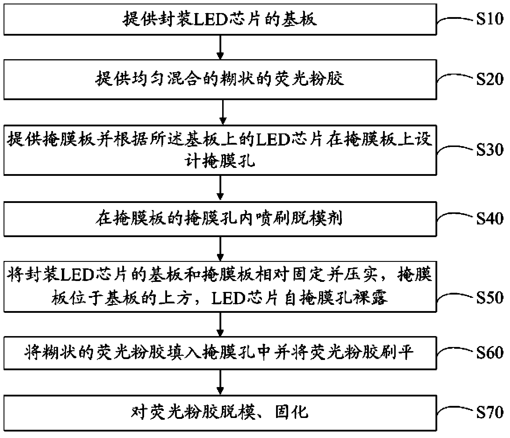
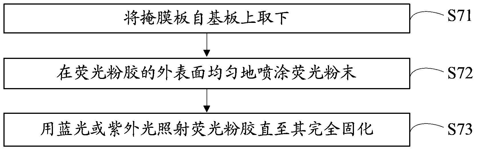
[0045] Please also refer to figure 2 , figure 2 It is a flow chart of the first embodiment of the demoulding and curing of phosphor glue in the phosphor coating method of the present invention, including the following steps:

[0046] S71, removing the mask plate 30 from the substrate 10;

[0047] S72, spraying phosphor powder evenly on the outer surface of the phosphor powder glue;

[0048] S73, irradiating the phosphor glue with blue light or ultraviolet light or heating the phosphor glue until it is completely cured.

[0049] The length of UV curing time is related to the colloid used, and a typical value in practical application is 30 seconds. Direct heating and curing is carried out by placing the phosphor glue in a vacuum oven. The heating temperature is generally 150 degrees Celsius and the heating time is 1 hour.

[0050] In this embodiment, the method of demoulding and then curing is adopted for the fluorescent powder glue brushed on the outside of the LED chip, wh...

no. 2 approach

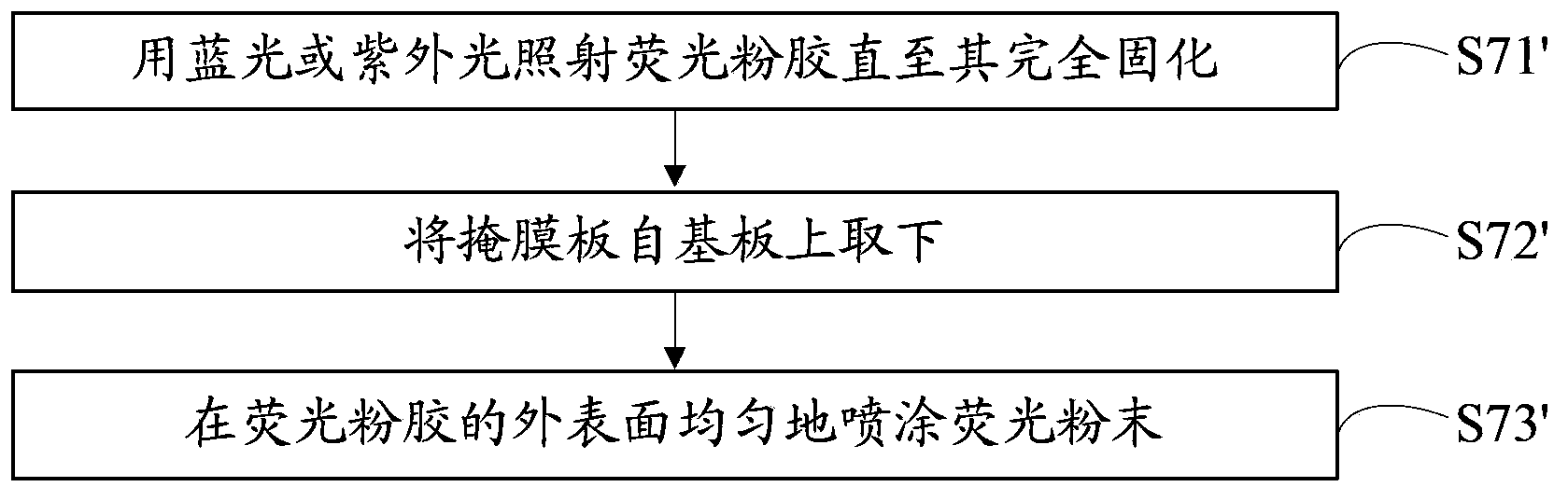
[0054] Please also refer to image 3 , image 3 It is a flow chart of the second embodiment of the demoulding and curing of phosphor glue in the phosphor coating method of the present invention, including the following steps:

[0055] S71', irradiating the phosphor glue with blue light or ultraviolet light until it is completely cured;

[0056] S72', the mask plate is taken off from the substrate;

[0057] S73', spraying fluorescent powder evenly on the outer surface of the fluorescent powder glue.

[0058] In this embodiment, the method of first curing and then demolding the phosphor glue brushed on the outside of the LED chip is applicable to the situation where relatively thin phosphor glue (that is, with a low viscosity coefficient) is prepared through step S20.

[0059] When the viscosity coefficient of the phosphor colloid is low, the phosphor colloid brushed on the outside of the LED chip through the mask plate is easy to flow, and it is not suitable for demoulding a...


PUM


Abstract

The invention discloses a phosphor coating method and an LED device. The phosphor coating method comprises the steps that pasty-state phosphor glue which is mixed uniformly is provided; a masking plate is provided and mask holes are designed in the masking plate according to LED wafers in a substrate; the substrate that packages LED wafers is fixed and compressed relative to the masking plate, the masking plate is positioned over the substrate, and the LED wafers are exposed of the mask holes; the pasty-state phosphor glue is filled into the mask holes and flattened via brushing; and the phosphor glue is demolded and solidified. The shape and thickness of a phosphor layer can be accurately controlled via the phosphor coating method, a uniform optical field can be obtained, and LED devices in the same batch are unified in light color.

Description

technical field [0001] The invention relates to a phosphor powder coating method in the field of photoelectric technology and a light emitting diode device manufactured by using the phosphor powder coating method. Background technique [0002] Light Emitting Diode (LED, Light Emitting Diode) is becoming the basis of semiconductor lighting because of its advantages of energy saving, environmental protection, and long life, and has attracted widespread attention. [0003] White light-emitting diodes usually use blue LEDs to excite yellow phosphors and / or red phosphors to form white light, or use violet LEDs to excite three primary color phosphors to synthesize white light. Therefore, the phosphor powder coating process is a key step in the manufacture of LED devices. [0004] A commonly used phosphor powder coating process is as follows: the phosphor powder and colloid are mixed in a certain proportion to form a powder slurry, and then the phosphor powder glue is coated on th...

Claims


Application Information

Patent Timeline
Patent Type & Authority Applications(China)
IPC IPC(8): H01L33/50H01L33/48
CPCH01L33/48H01L33/505H01L33/508H01L2933/0041
Inventor 柴广跃刘文
Owner SHENZHEN UNIV
Why Eureka
Try Eureka