Multi-degree of freedom adjustment structure for security robot

A technology for adjusting structures and robots, applied in manipulators, manufacturing tools, etc., can solve problems such as not being able to meet the working requirements of security robots, slow response speed, and difficult to control the stroke

Pending Publication Date: 2018-06-22
中山火炬高新企业孵化器有限公司
View PDF1 Cites 4 Cited by
  • Summary
  • Abstract
  • Description
  • Claims
  • Application Information

AI Technical Summary

Problems solved by technology

[0003] At present, there is a kind of authorized patent called "monitoring robot that is easy to move", application number 201710821463.8. Its lifting structure is to drive the lifting platform through a hydraulic lift. Difficult to control, slow response speed, cannot meet the working needs of security robots
[0004] At the same time, when the existing security robot monitors different terrains, how to realize the power supply to the camera at the top and the transmission of the video signal when the push rod is raised or lowered is a difficult problem in the existing design

Method used


Image

  • Multi-degree of freedom adjustment structure for security robot
  • Multi-degree of freedom adjustment structure for security robot
  • Multi-degree of freedom adjustment structure for security robot

Examples


Embodiment 1

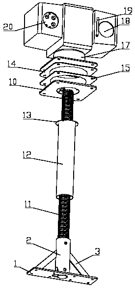
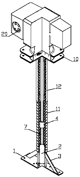
[0037] Such as Figure 3-4 As shown, the electric push rod includes a drive motor 4, a drive motor support tube 5, a worm 6, a lifting screw 7, and a travel switch 8. The drive motor support tube 5 is arranged in the electric push rod, and the drive motor support tube 5 The installation consists of a driving motor 4, the output shaft of the driving motor 4 is connected with the worm 6, the worm 6 is connected with the lifting screw 7, the travel switch 8 is arranged at the end of the driving motor support tube 5, and the travel switch 8 is controlled by an external controller 9 is connected with the driving motor 4, and receives the signal sent by the travel switch 8 through the external controller 9. The external controller 9 controls the forward rotation or reverse rotation of the driving motor 4, and the driving motor 4 rotates to drive the worm 6 on the supporting rod of the driving motor 4. Moving up, the worm 6 rotates to drive the lifting screw 7 to move, realizing the ...

Embodiment 2

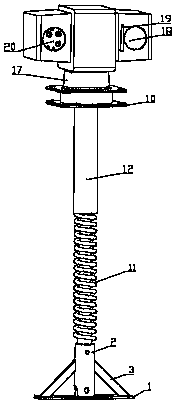
[0041] Such as Figure 5 As shown, on the basis of Embodiment 1, the multi-degree-of-freedom adjustment of the security robot is realized by adding the electric pan / tilt 17 and the two-degree-of-freedom adjustment of the camera. When the electric push rod moves up and down, the camera moves according to It is necessary to perform circular or pitch motion synchronously. When the pan / tilt 17 receives the up and down action voltage from the built-in controller 21, the vertical motor rotates, and the vertical transmission wheel is driven to rotate through the reduction box; when it receives the left and right action voltage When voltage is applied, the horizontal motor rotates and drives the horizontal gear plate at the bottom of the cloud platform 17 to rotate through the reduction box. The cloud platform 17 is provided with a vertical stop bolt, and the cloud platform 17 realizes the limit function by two micro switches respectively. When the preset limit bolt is reached, the mi...


PUM


Abstract

The invention relates to a multi-degree of freedom adjustment structure for a security robot, and belongs to the field of security robots. The multi-degree of freedom adjustment structure for the security robot comprises a fixing support seat, an electronic push rod, a spring wire, a sleeve, a shock absorption platform, a cloud platform and a camera, and the electronic push rod includes a drivingmotor, a driving motor supporting tube, a worm, a lifting screw rod and a stroke switch. The invention provides the multi-degree of freedom adjustment structure for the security robot, and the multi-degree of freedom adjustment of the camera of the security robot is achieved to meet different working requirements; the drive motor drives the screw rod to move up and down, the stroke control is moreprecise, and the lifting reaction speed is faster; the conditions that the camera can be powered and video signal transmission is normal can be ensured while the lifting mechanism moves up and down,and the case that the disconnection of a wire caused by the movement of the push rod affects the normal operation of the security robot is avoided.

Description

technical field [0001] The invention belongs to the field of security robots, and in particular relates to a multi-degree-of-freedom adjustment structure for security robots. Background technique [0002] After investigation, it is found that the shooting range of the cameras on the security robots currently on the market is mostly 360 degrees in circumference and pitch rotation. [0003] At present, there is a kind of authorized patent called "monitoring robot that is easy to move", application number 201710821463.8. Its lifting structure is to drive the lifting platform through a hydraulic lift. It is not easy to control, and the reaction speed is slow, which cannot meet the working needs of security robots. [0004] At the same time, when the existing security robot monitors different terrains, how to realize the power supply to the camera at the top and the transmission of the video signal when the push rod is raised or lowered is a difficult problem in the existing des...

Claims


Application Information

Patent Timeline
Patent Type & Authority Applications(China)
IPC IPC(8): B25J19/02
CPCB25J19/023
Inventor 龙亿刘志杰吴润锋
Owner 中山火炬高新企业孵化器有限公司
Why Eureka
Try Eureka