Novel process for LED fluorescent coating

A fluorescent powder and new process technology, applied in the direction of electrical components, circuits, semiconductor devices, etc., can solve the problems of inconsistent distance between LED chips, uneven light color, and light color shift of LED components, so as to improve LED light intensity, The effect of uniform light spot or light color and thin mixed thickness

Inactive Publication Date: 2009-07-08
ZHONGTU ENERGY CONSERVATION TECH CHANGZHOU
View PDF0 Cites 6 Cited by
  • Summary
  • Abstract
  • Description
  • Claims
  • Application Information

AI Technical Summary

Problems solved by technology

[0004] The above LED phosphor mixture dispensing process has several disadvantages. First, the phosphor mixture will be affected by the shape of the cup mouth of the bracket and produce a yellow or blue circle phenomenon, because the cup mouth of the bracket currently used is round and the LED The chip is square, and the distance from the LED chip to each point of the circle is inconsistent. The color near the LED chip is bluish and the color far away from the LED chip is yellowish.
Second, because the dispensing method of the dispensing machine is to use gravity to let the silica gel or epoxy resin containing the phosphor flow and then wrap the LED chip, so the thickness of the phosphor is too large and it cannot be evenly distributed on the LED light-emitting surface. It will cause uneven wavelength conversion, which will cause light color shift and uneven light color of LED components.

Method used


Image

  • Novel process for LED fluorescent coating
  • Novel process for LED fluorescent coating
  • Novel process for LED fluorescent coating

Examples


Embodiment 1

[0027] The LED fluorescent powder coating process method of the present invention is carried out according to the following steps:

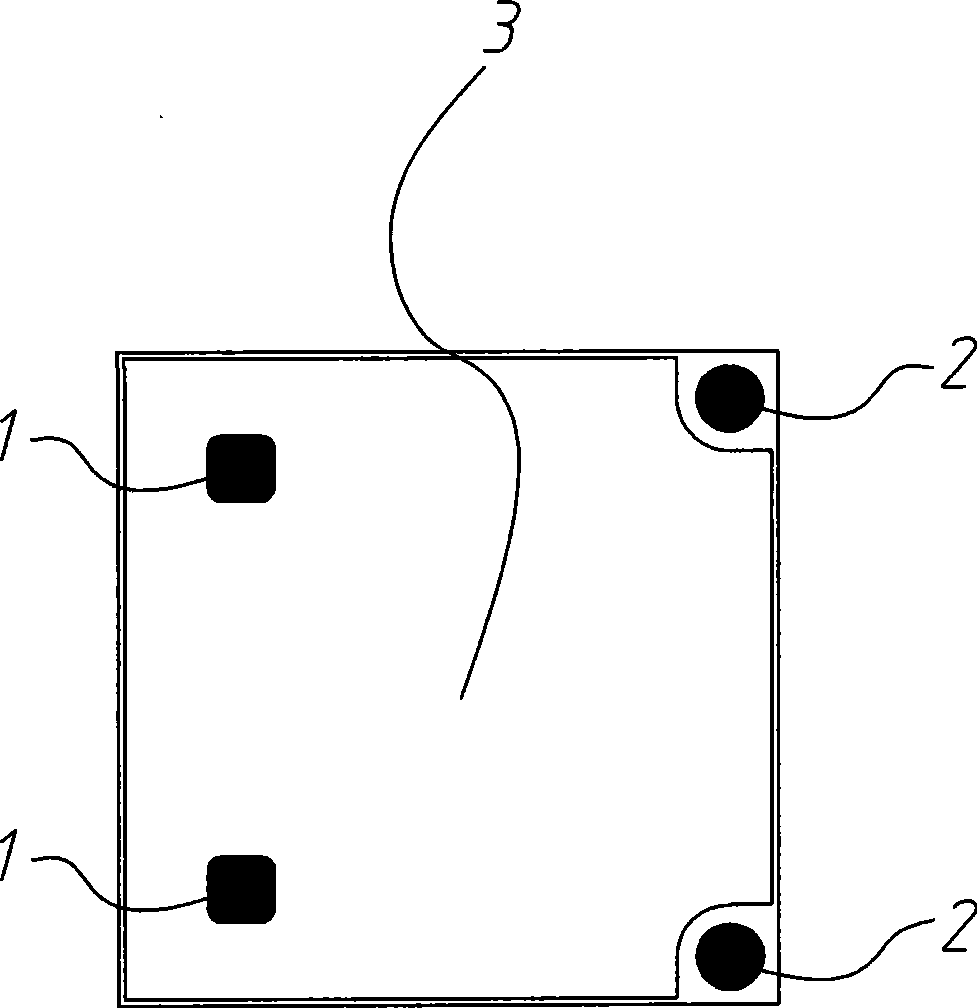
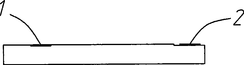
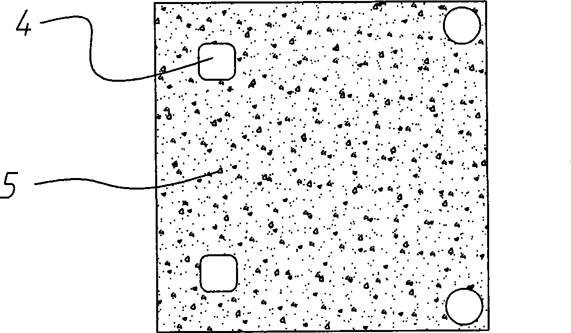
[0028] first as image 3 As shown, the columnar hole membrane structure permeable membrane 5 obtained by using polycarbonate or polyester materials through the nuclear etching method is punched 4 according to the position of the positive and negative electrodes PAD1 and 2 of the LED chip 3 gold wire bonding; the hole 4 is punched The permeable membrane 5 is cut according to the size of the LED wafer 3; Figure 4 , Figure 5 As shown, the permeable membrane 5 that has been punched and cut is placed on the top of the LED chip 3; Figure 6 As shown, use a dispensing machine to mix phosphor powder and silica gel at a mass ratio of 1:1.25 to 1:1000. Put 6 spots of the phosphor powder mixture on the above-mentioned permeable membrane 5; Figure 7 As shown, the above phosphor powder mixture 6 is cured and the permeable membrane 5 is peeled off, leavi...

Embodiment 2

[0030] The LED fluorescent powder coating process method of the present invention is carried out according to the following steps:

[0031] first as image 3 As shown, the columnar hole membrane structure permeable membrane 5 obtained by using polycarbonate or polyester materials through the nuclear etching method is punched 4 according to the position of the positive and negative electrodes PAD1 and 2 of the LED chip 3 gold wire bonding; the hole 4 is punched The permeable membrane 5 is cut according to the size of the LED wafer 3; Figure 4 , Figure 5 As shown, the permeable membrane 5 that has been punched and cut is placed on the top of the LED chip 3; Figure 6 As shown, use a dispensing machine to mix phosphor powder and epoxy resin at a mass ratio of 1:1.25 to 1:1000, and put 6 spots of the phosphor powder mixture on the above-mentioned permeable membrane 5; Figure 7 As shown, the above phosphor powder mixture 6 is cured and the permeable membrane 5 is peeled off, ...


PUM


Abstract

The invention relates to a novel LED fluorescent powder coating process, which comprises the following steps: covering an LED wafer with an osmosis membrane; and applying the mixture solution of silica gel or epoxy resin and fluorescent powder on the LED wafer through osmosis effect of the osmosis membrane and deposition of the fluorescent powder. The process can ensure that the fluorescent powder mixture solution is directly cured on the LED wafer according to the size of the LED wafer while not being influenced by the size of a bracket opening, thereby uniformly applying the fluorescent powder mixture on the LED waver to prevent the occurrence of blue or yellow blocks or rings in the optical spots or color of light emitted by the LED lamp. In addition, the mixture of silica gel or epoxy resin and fluorescent powder has small thickness, which can enhance the light intensity of the LED.

Description

technical field [0001] The invention relates to a process method for LED fluorescent powder coating. Background technique [0002] In daily life, we often come into contact with various lamps and lanterns. Among them, LEDs (light-emitting diodes) are widely used because of their long life, energy saving, good shock resistance, fast response, high reliability, environmental protection and safety, etc. With the advancement of technology, the light efficiency of LED has been improved to a certain extent. [0003] At present, part of the process of phosphor coating involved in the LED packaging process is to use a dispenser to dispense glue on the cup mouth of the bracket after the positive and negative gold wire bonding process of the LED chip. The specific process method is as follows: the first step is to fix the LED chip on the bracket with the cup mouth, the second step is to bond the positive and negative electrodes of the LED chip with gold wire, the third step is to mix...

Claims


Application Information

Patent Timeline
Patent Type & Authority Applications(China)
IPC IPC(8): H01L33/00
Inventor 姚志图宣扬
Owner ZHONGTU ENERGY CONSERVATION TECH CHANGZHOU
Why Eureka
Try Eureka