Multifunctional automatic hook bouncing fish float

A snap hook fish, multi-functional technology, used in fishing, fishing accessories, animal husbandry and other directions, can solve the problem of not being able to catch multiple hand rods at the same time, not knowing when to start the rod, and difficult to catch fish.

Inactive Publication Date: 2019-06-04
杨光献
View PDF0 Cites 0 Cited by
  • Summary
  • Abstract
  • Description
  • Claims
  • Application Information

AI Technical Summary

Problems solved by technology

[0002] Fishing is an outdoor sport that is very popular among people. Floats are an indispensable fishing tool in fishing, and they are also a tool for transmitting information about fish bites. The commonly used floats can basically be divided into two types, one is non-luminous floats , and the other is a luminous float, but these two floats have common shortcomings. The first is that it is difficult for novices to catch fish without experience, because they don’t know when to lift the pole (lifting the pole is to quickly pull up the fishing line to hook fish mouth), often misses the best time for lifting the pole, the bait will be eaten by the fish, and then spit out the hook and escape, or the hook is not in the fish mouth at all when lifting the pole, and the pole cannot be lifted Fish (fishing is to hook the fish), the second disadvantage is that the above two kinds of floats cannot catch multiple hand poles at the same time, because when fishing, it is necessary to observe the condition of the floats at all times, and lift the poles immediately when there is a chance. not even a second

Method used


Image

  • Multifunctional automatic hook bouncing fish float
  • Multifunctional automatic hook bouncing fish float
  • Multifunctional automatic hook bouncing fish float

Examples


Embodiment Construction

[0024] In order to facilitate the examiner to further understand the purpose of the present invention, the preferred embodiment and drawings are described in detail as follows:

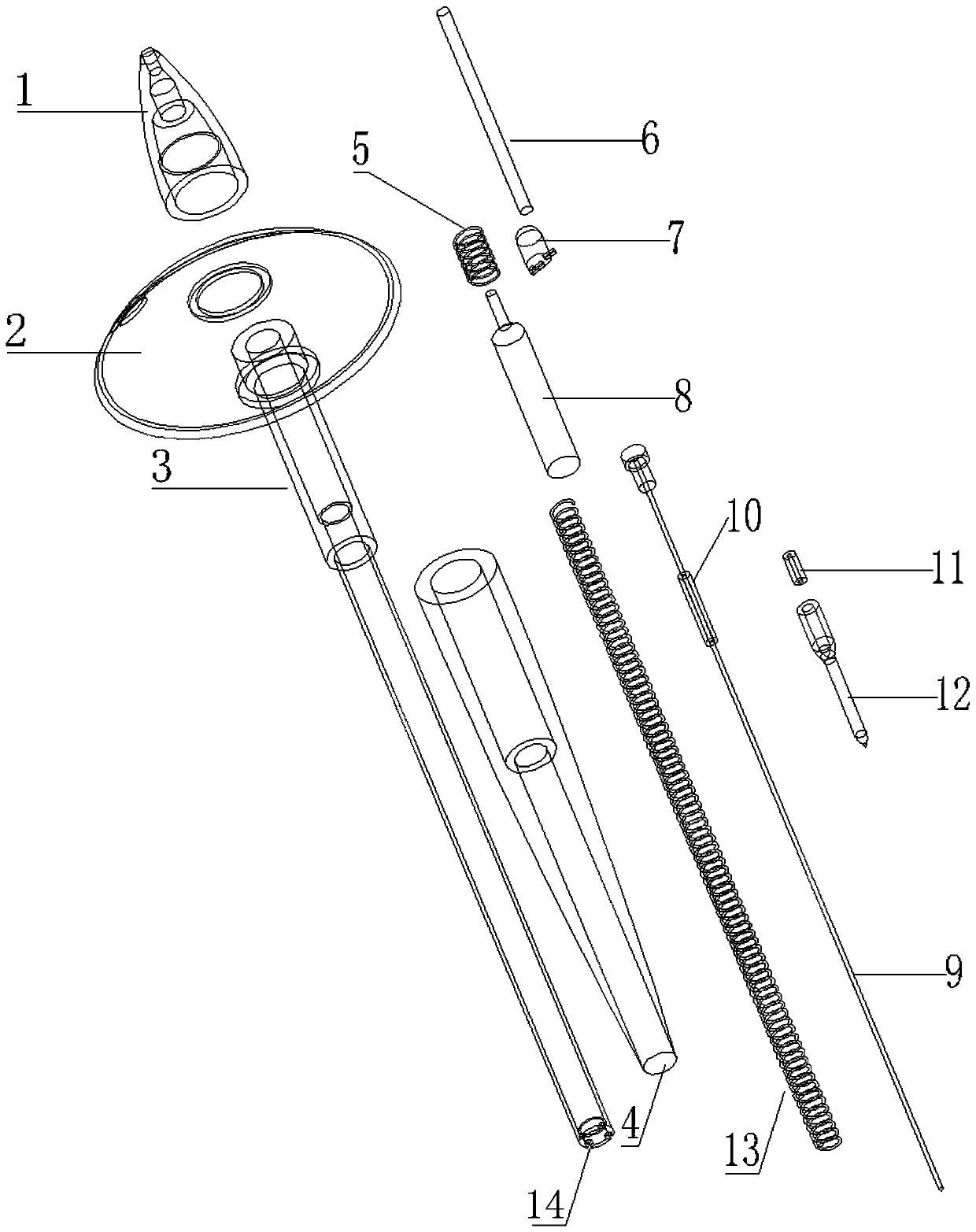
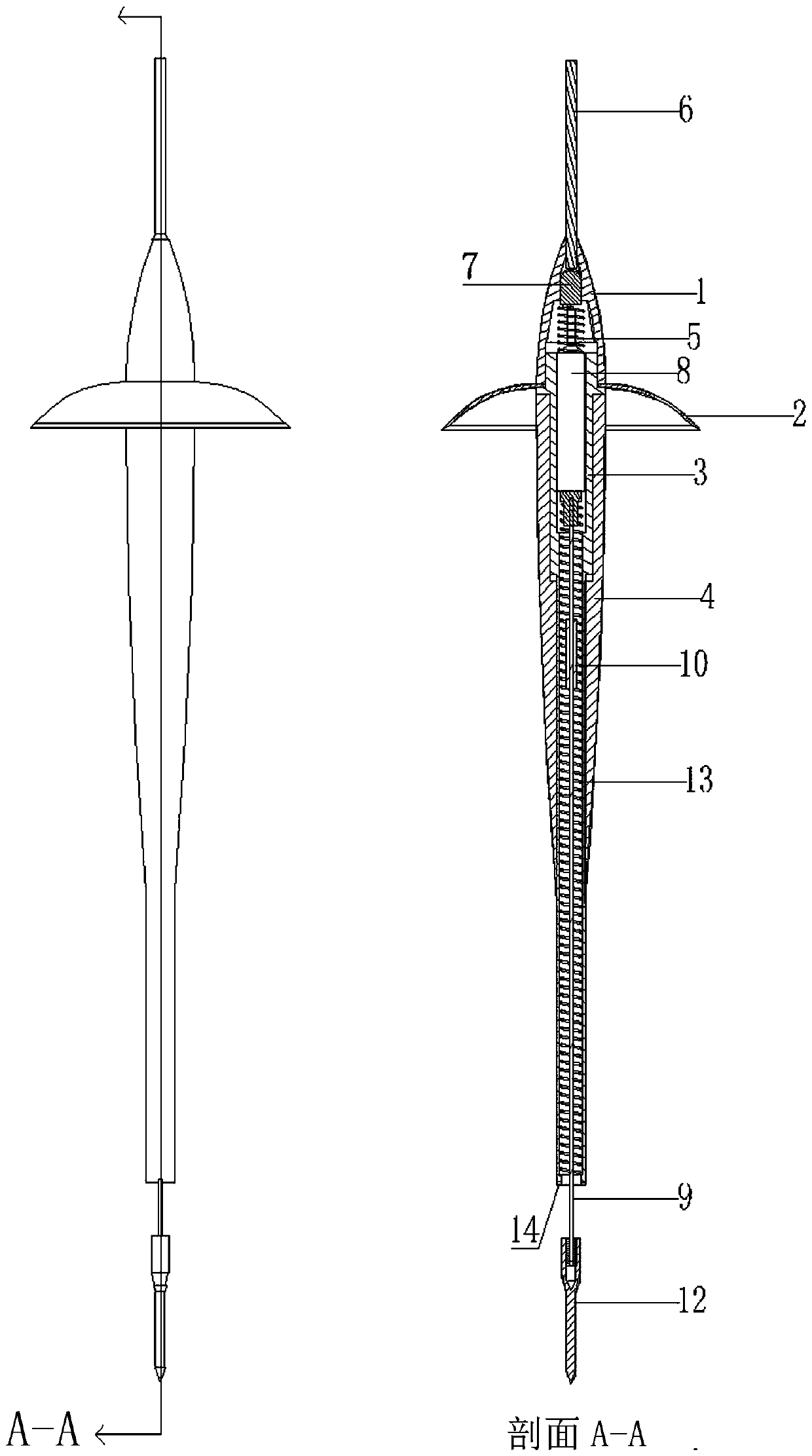
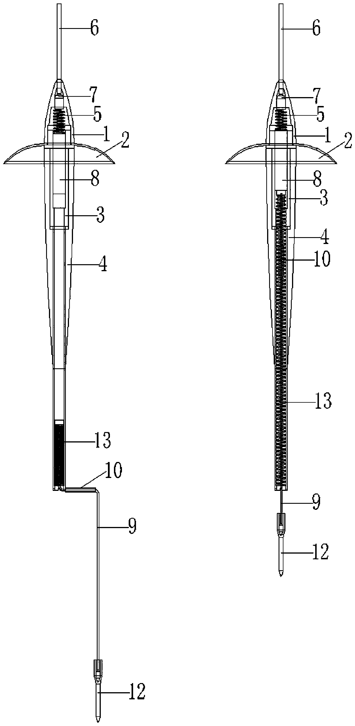
[0025] Such as image 3 , 4 , 7, when fishing is needed, the trigger line 9 is pulled down to the bottom, then the trigger line 9 is rotated 90 degrees, and the cylinder 10 is stuck on the side of the draw-in groove 14. One end of the trigger wire 9 is connected to make the force spring 13 compressed. When the force spring 13 is pressed down, the battery 8 is pushed back by the conductive spring 5, so that one electrode of the battery 8 and the LED lamp 7 are bent inward. The lamp pin of the lamp is disconnected, and the LED lamp 7 is extinguished.

[0026] Such as Figure 4 , as shown, when fishing for different sizes and different fish species, it is necessary to adjust different sensitivities. At this time, a plurality of slots 14 with different depths are arranged at the bottom of the floating ...


PUM


Abstract

The fish float includes an LED lamp, a light guide column, a battery, a conductive spring, a power generation spring, a triggering wire, a circular column, a float body, a resistance member and a fishfloat seat plug pin; The fish float is characterized in that the light guide column is installed on the top of the float body; the external of the float body is sleeved by the resistance member; theinternal of the float body is provided with the power generation spring; one end of the spring is connected to the triggering wire, and the other end of the spring is fixed on the float body; one endof the light guide column is provided with the LED lamp; one foot of the LED lamp is connected to the conductive spring; the battery is installed between the conductive spring and the power generationspring; the circular column is fixed at a proper position on the triggering wire; and the fish float seat plug pin is installed on the tail end of the triggering wire. When a fish pulls bait, a hookcan be rapidly bounced to hook the mouth of the fish in an extremely short time, so that the fish can be captured; and the lamp can be lighted to give a prompt after the fish is hooked, so that the fish float can completely substitute common fish floats.

Description

technical field [0001] The invention relates to a fishing tool, which is a multifunctional automatic spring hook float. Background technique [0002] Fishing is an outdoor sport that is very popular among people. Floats are an indispensable fishing tool in fishing, and they are also a tool for transmitting information about fish bites. The commonly used floats can basically be divided into two types, one is non-luminous floats , and the other is a luminous float, but these two floats have common shortcomings. The first is that it is difficult for novices to catch fish without experience, because they don’t know when to lift the pole (lifting the pole is to quickly pull up the fishing line to hook fish mouth), often misses the best time for lifting the pole, the bait will be eaten by the fish, and then spit out the hook and escape, or the hook is not in the fish mouth at all when lifting the pole, and the pole cannot be lifted Fish (fishing is to hook the fish), the second d...

Claims


Application Information

Patent Timeline
Patent Type & Authority Applications(China)
IPC IPC(8): A01K93/02F21V33/00F21V8/00F21V23/04
Inventor 杨光献
Owner 杨光献
Why Eureka
Try Eureka