Heat distribution pipeline with safety catch

A technology of thermal pipelines and safety plugs, which is applied in the direction of pipeline systems, pipe components, valve operation/release devices, etc., and can solve the problems that the staff cannot quickly know the leakage, the safety is blocked, and the hot water is easy to enter the insulation layer.

Inactive Publication Date: 2021-08-10
陈定丽
View PDF1 Cites 0 Cited by
  • Summary
  • Abstract
  • Description
  • Claims
  • Application Information

AI Technical Summary

Problems solved by technology

[0005] Because the thermal pipeline needs to transport hot water, and the thermal pipeline is usually divided into a pipeline and an insulation layer. When a leak occurs inside the thermal pipeline, hot water easily enters the interior of the insulation layer, causing the staff to be unable to quickly know the leak, and the thermal pipeline Unable to form a safety barrier inside when hot water leaks

Method used


Image

  • Heat distribution pipeline with safety catch
  • Heat distribution pipeline with safety catch
  • Heat distribution pipeline with safety catch

Examples


Embodiment

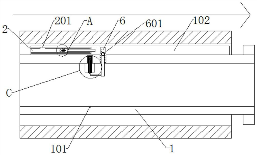
[0033] as attached figure 1 to attach Figure 7 Shown: a heat pipe with a safety plug, including a shell 1, the upper and lower ends of the inner wall of the shell 1 are respectively embedded with a groove 101 and an inner cavity 102;

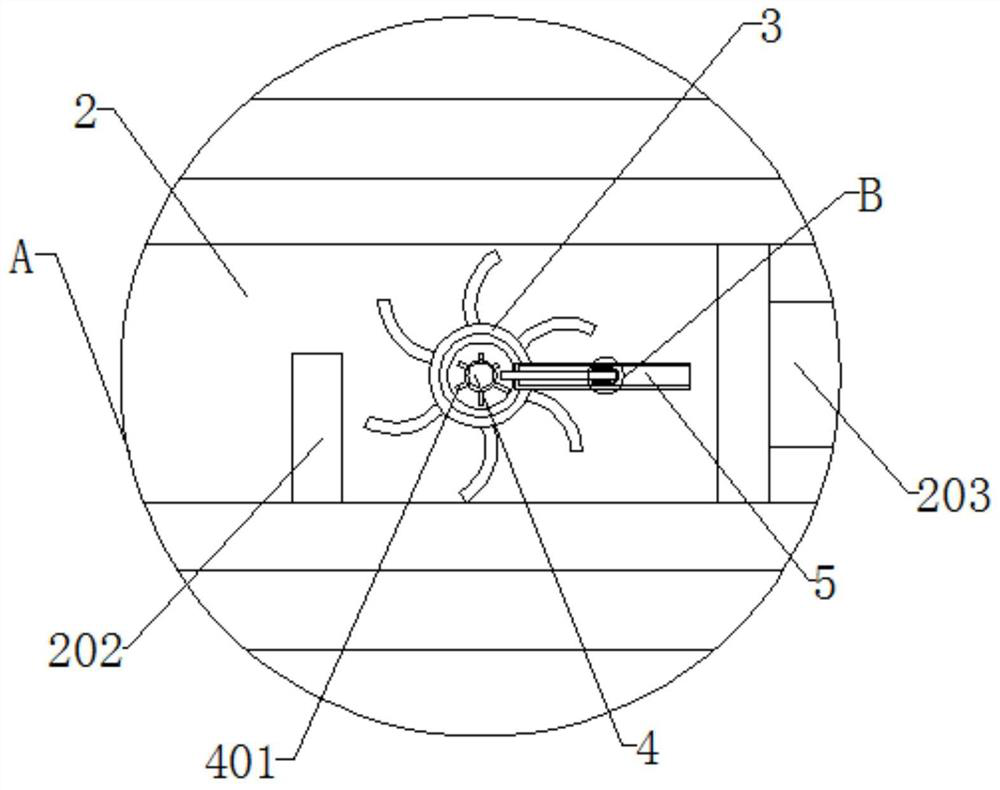
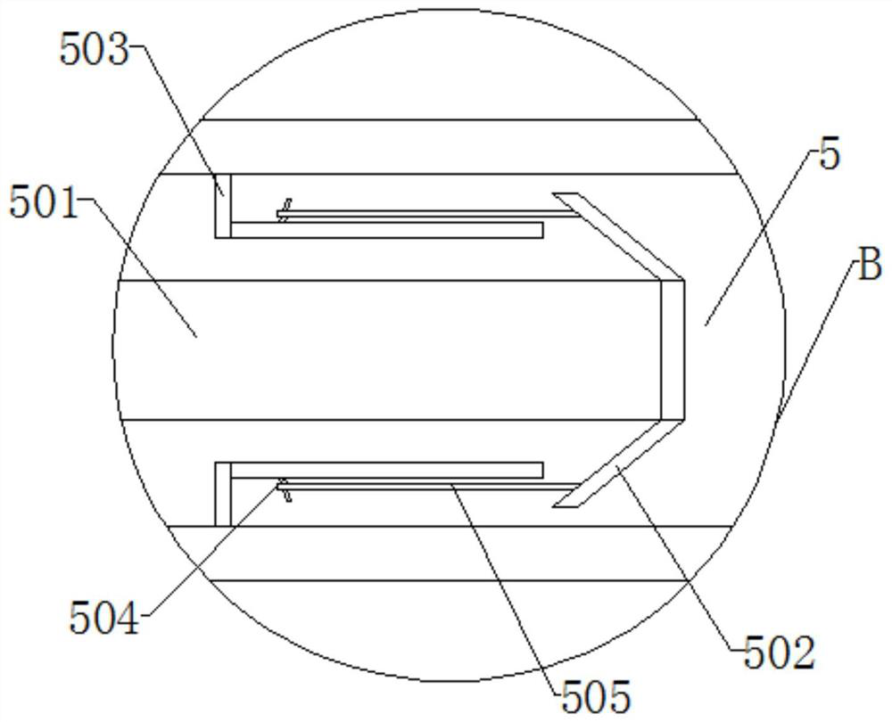
[0034] A water inlet frame 2 is installed inside the cavity 102, a hole 201 is embedded in the upper end of the water inlet frame 2, a baffle plate 202 is installed at the lower end of the hole 201, and a slide bar 203 is slidably connected to the other side of the water inlet frame 2, The side of the water inlet frame 2 close to the slide bar 203 rotates with an outer bearing 3, the outer side of the outer bearing 3 is surrounded by a fan blade 301, and one side of the outer bearing 3 is movably nested with a fixed cylinder 302, and the internal rotation of the fixed cylinder 302 is connected to There is an inner bearing 4, blades 401 are installed on the outside of the inner bearing 4, a bracket 5 is installed on the side of the fixed cylind...


PUM


Abstract

The invention provides a heat distribution pipeline with a safety catch. The heat distribution pipeline with the safety catch comprises a shell, wherein a groove and an inner cavity are embedded in the upper end and the lower end of the inner wall of the shell correspondingly; a water inlet frame is installed in the inner cavity; a hole is embedded in the upper end of the water inlet frame; a baffle is installed at the lower end in the hole; a sliding rod is slidably connected to the other side in the water inlet frame; an outer bearing is rotationally arranged on the side, close to the sliding rod, in the water inlet frame; the sliding rod rapidly impacts one side of an upper swing frame when sliding; the upper swing frame drives a lower swing frame to swing through a rotating ball; and the lower end of the lower swing frame tilts at an angle to be extruded to the lower end of a sliding disc. Since a clamping frame is set in an isosceles trapezoid, a limiting strip at the upper end of the sliding disc can be conveniently bounced at the upper end of the clamping frame, then the sliding disc can quickly slide downwards in a telescopic disc, and a magnet at the lower end of the sliding disc is quickly embedded into the groove, so that the interior of the heat distribution pipeline can be blocked when leakage occurs.

Description

technical field [0001] The invention relates to the technical field of pipelines, in particular to a thermal pipeline with a safety plug. Background technique [0002] Heat pipe network, also known as heat pipe, starts from the boiler room, direct-fired machine room, heating center, etc., and leads from the heat source to the heat supply pipe of the building's heat entrance. Multiple heat supply pipes form a pipe network, and the design of the heating water medium Design of the following heating networks with pressure less than or equal to 2.5MPa and design temperature less than or equal to 200°C; design pressure of heating steam medium less than or equal to 1.6MPa and design temperature less than or equal to 350°C; [0003] Regarding the thermal pipeline, after searching, it was found that there is a patent number CN201711425052.3 for a thermal pipeline with an optical cable. This kind of thermal pipeline with an optical cable can be used by the optical cable by laying the ...

Claims


Application Information

Patent Timeline
Patent Type & Authority Applications(China)
IPC IPC(8): F16L55/10F16L55/105F16K3/02F16K3/30F16K3/314F16K27/04F16K31/46F17D5/02F17D3/01
CPCF16K3/0281F16K3/30F16K3/314F16K27/044F16K31/465F16L55/1022F16L55/105F17D3/01F17D5/02
Inventor 陈定丽
Owner 陈定丽
Why Eureka
Try Eureka