Lifting workbench for maintenance of electric equipment

A technology for raising and lowering workbenches and electric equipment, which is applied in the directions of lifting frames, safety devices for lifting equipment, lifting devices, etc., can solve the problem of damage to the service life of the movable connection point of the fork bracket, safety and stability cannot be safely guaranteed and operated. There are safety hazards and other problems for maintenance personnel, to achieve the effect of saving manpower, simple structure, and preventing falling objects from hurting people

Inactive Publication Date: 2019-06-04
GUILIN JIEYU ENVIRONMENTAL PROTECTION SCI & TECH
View PDF0 Cites 4 Cited by
  • Summary
  • Abstract
  • Description
  • Claims
  • Application Information

AI Technical Summary

Problems solved by technology

Can be widely used in equipment maintenance, stations, docks, bridges, halls, indoor and outdoor mechanical installation, equipment maintenance, building maintenance, scissor lift platform is equipped with fork-shaped brackets, only using fork-shaped brackets will seriously damage the fork-shaped The service life of the movable connection point between the bracket and the fork-shaped bracket, the long-term bearing capacity is too large, the operating capacity of the movable connection point will be gradually reduced or even damaged, and there will be safety hazards for the operation and maintenance personnel in the work project. Supported by a fork-shaped bracket, its safety and stability cannot be guaranteed, and the scissor lift platform can only send the operating platform to a height suitable for operation and maintenance, but in the maintenance area, some parts that need maintenance are of different heights. Sending the operating platform to a suitable height for operation and maintenance is often not enough to meet the operating needs, so it is necessary to install an auxiliary operating platform on the lifting platform to adapt to the height of different maintenance components

Method used


Image

  • Lifting workbench for maintenance of electric equipment
  • Lifting workbench for maintenance of electric equipment
  • Lifting workbench for maintenance of electric equipment

Examples


Embodiment Construction

[0015] The following will clearly and completely describe the technical solutions in the embodiments of the present invention with reference to the accompanying drawings in the embodiments of the present invention. Obviously, the described embodiments are only some, not all, embodiments of the present invention. Based on the embodiments of the present invention, all other embodiments obtained by persons of ordinary skill in the art without making creative efforts belong to the protection scope of the present invention.

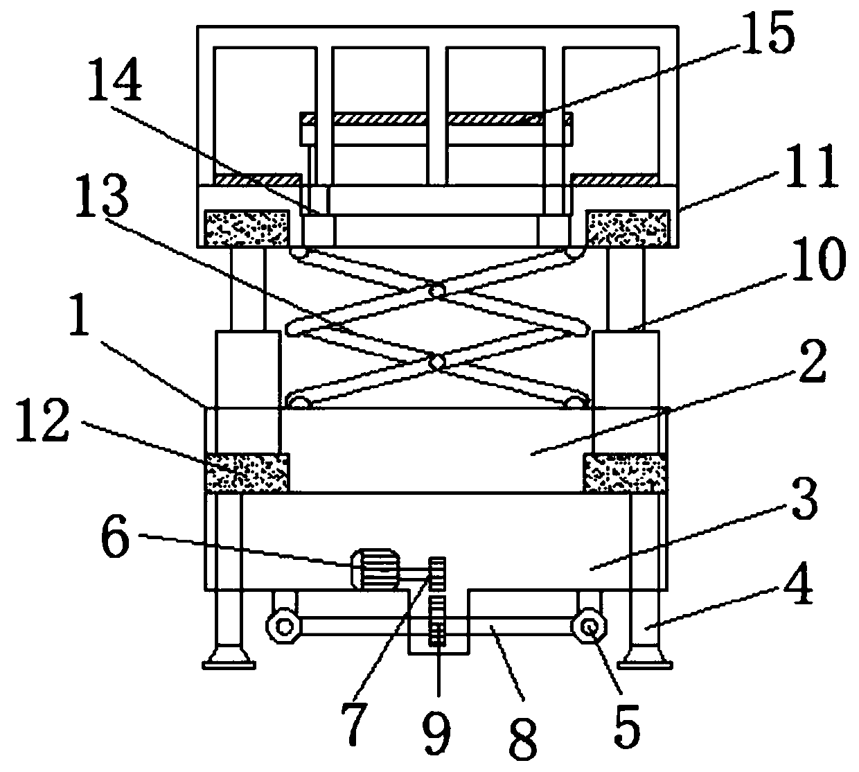
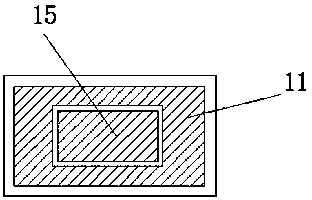
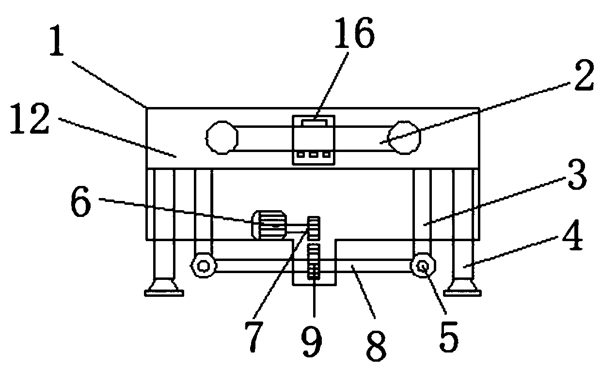
[0016] The present invention provides such Figure 1-3 A lifting workbench for electric equipment maintenance is shown, which includes a moving box 1, the moving box 1 includes a force-bearing base 2 and an installation box 3, and the bottom of the installation box 3 is provided with four hydraulic feet 4 , and the bottom of the installation box 3 and the inner side of the hydraulic support foot 4 are horizontally and symmetrically provided with two sets of dr...


PUM


Abstract

The invention discloses a lifting workbench for maintenance of electric equipment. The lifting workbench comprises a movable box body, wherein the movable box body comprises a stressed base and a mounting box, four hydraulic supporting legs are arranged at the bottom of the mounting box, a driving motor is arranged inside the mounting box, an output shaft of the driving motor is fixedly connectedwith a small wheel disc through a coupler, a driving rod is arranged between two driving wheels on the rear side of the mounting box, a large wheel disc meshed with the small wheel disc is arranged onthe driving rod, the stressed base is connected with an operation table through an electric hydraulic jack, a fork type support is arranged between the operation table and the stressed base and located on the inner side of the electric hydraulic jack through support movable wheels, an electric telescopic rod is arranged inside the operation table, and an auxiliary operation table is arranged on the electric telescopic rod. The lifting workbench is simple in structure and is provided with the auxiliary operation table so as to be adaptable to the heights of different maintenance parts, operation is convenient, operation safety is improved, the labor is saved, and the working efficiency is improved.

Description

technical field [0001] The invention belongs to the technical field of electric power, and in particular relates to a lifting workbench for electric equipment maintenance. Background technique [0002] The scissor lift platform is a kind of special equipment for vertical lifting, which is widely used indoors and outdoors for high-altitude operations. Can be widely used in equipment maintenance, stations, docks, bridges, halls, indoor and outdoor mechanical installation, equipment maintenance, building maintenance, scissor lift platform is equipped with fork-shaped brackets, only using fork-shaped brackets will seriously damage the fork-shaped The service life of the movable connection point between the bracket and the fork-shaped bracket, the long-term bearing capacity is too large, the operating capacity of the movable connection point will be gradually reduced or even damaged, and there will be safety hazards for the operation and maintenance personnel in the work project....

Claims


Application Information

Patent Timeline
Patent Type & Authority Applications(China)
IPC IPC(8): B66F7/06B66F7/20B66F11/04B66F17/00
Inventor 杨军
Owner GUILIN JIEYU ENVIRONMENTAL PROTECTION SCI & TECH
Why Eureka
Try Eureka