Rod end bearing extreme temperature test fixture and its test method

A technology of extreme temperature and test fixture, applied in the direction of mechanical bearing testing, etc., can solve the problems of difficult to ensure the center of the fixture, prone to eccentricity, waste of money, time and resources, etc., to improve the efficiency of equipment use, ensure accuracy and accuracy, reduce The effect of the frequency of the tour

Active Publication Date: 2020-07-10
CHINA AERO POLYTECH ESTAB
View PDF5 Cites 0 Cited by
  • Summary
  • Abstract
  • Description
  • Claims
  • Application Information

AI Technical Summary

Problems solved by technology

[0003] The existing extreme temperature test platform has poor design versatility and cannot realize the sharing of multiple types of bearings, so that when completing the extreme temperature test of different types of bearings, it is necessary to frequently replace the test fixtures, thus requiring various specifications of fixtures to complete the test, resulting in A great waste of funds, time and resources; in addition, the existing extreme temperature test device, the center of the transmission rod and the inner ring of the bearing is not easy to align, and the problem of eccentricity is prone to occur. The eccentricity will cause the inner ring of the bearing to bear additional radial force, and the bearing The service life is reduced, which seriously affects the accuracy of the test results; the rod end bearing is not easy to install and fix, and the centering of the fixture is not easy to ensure when the test equipment is installed. When the box wall is connected to the bearing in the box, the installation process is relatively cumbersome and laborious, and it is easy to cause interference between various parts of the test fixture, which greatly prolongs the test preparation time

Method used


Image

  • Rod end bearing extreme temperature test fixture and its test method
  • Rod end bearing extreme temperature test fixture and its test method

Examples


Embodiment Construction

[0029] In order to detail the technical content, structural features, achieved goals and effects of the present invention, the following will be described in detail in conjunction with the accompanying drawings.

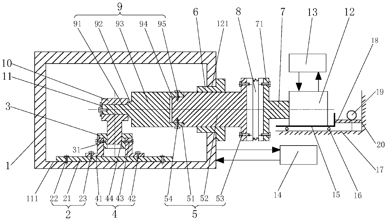
[0030] The invention provides a rod end bearing extreme temperature test fixture, such as figure 1 As shown, it includes a fixed table 2, an adapter seat 3, a base 4, a box-through connecting shaft 5, a plastic sleeve 6, a motor shaft 7, a coupling 8, a fixture connecting shaft 9 and a retaining ring 11. The fixed table 2 is provided with Two sets of threaded holes, and each set of threaded holes are evenly distributed on two concentric circles, the plate body 21 of the fixing table 2 is fixedly connected to the bottom plate 111 of the temperature test chamber 1 through the first set of threaded holes 22 with screws, The base 4 is provided with a third threaded hole group 42, a fourth threaded hole group 43 and an adapter mounting hole 44, and screws pass through the...


PUM


Abstract

The invention relates to a rod end bearing limit temperature test fixture and a test method thereof. The rod end bearing limit temperature test fixture comprises a fixing table, an adapter seat, a base, a box passing connection shaft, a plastic sleeve, a motor shaft, a coupling, a fixture connection shaft and a retaining ring, wherein the adapter seat is mounted on the base; the base is mounted onthe fixing table; during the test, a tested bearing is connected to the inner threaded hole of the adapter seat through the outer thread of the rod end, and the outer diameter of the adapter seat ismatched with the inner hole of the base, a screw passing through the retaining ring is clamped to the fixture connection shaft, and the shaft is driven by the motor to realize the radial rotation of the inner ring of the tested bearing; and the fixture connection shaft is provided with a groove, the box passing connection shaft is provided with a connection shoulder, the box passing connection shaft passes through the temperature test box to be connected with the motor through the coupling, and the box passing connection shaft passes through the temperature test box through the plastic sleeve.The fixture has a simple structure, disassembly is facilitated, the mounting preparation time is shortened, and the device use efficiency is improved.

Description

technical field [0001] The invention belongs to the field of testing mechanical equipment, and in particular relates to a fixture for extreme temperature testing of rod end bearings and a testing method thereof. Background technique [0002] The extreme temperature test is one of the important items in the qualification test of a series of rod end rolling bearings such as aviation rod end double row roller bearings. Taking the rod end double row roller bearing for aviation as an example, the limit temperature test is in accordance with the relevant requirements of the general specification for this type of bearing: the bearing to be tested is placed in the environment with the lowest service temperature of -55°C, and the temperature is 3r / min±1r / min. Rotate at a speed of 100h, adjust the temperature to 121°C, and run for 100h. This test platform can not only meet the basic requirements of the above tests, but also meet the requirements of a wider range of relevant temperatu...

Claims


Application Information

Patent Timeline
Patent Type & Authority Patents(China)
IPC IPC(8): G01M13/04
Inventor 宋超边智滕明林晶赵颖春
Owner CHINA AERO POLYTECH ESTAB
Why Eureka
Try Eureka