Optical Fiber Panel and Its Debugging Method

A technology of optical fiber panel and debugging method, which is applied in the direction of bundled optical fibers, etc., can solve the problems that optical fibers cannot transmit optical fibers, low light transmittance, and poor image resolution, so as to avoid low image resolution and high image contrast. The effect of stable performance and interface performance

Active Publication Date: 2020-08-14
SHANGHAI OXI TECH
View PDF13 Cites 0 Cited by
  • Summary
  • Abstract
  • Description
  • Claims
  • Application Information

AI Technical Summary

Problems solved by technology

[0004] However, in the fiber optic panel, the cladding pigments of the optical fiber can penetrate each other, causing the black pigment to penetrate into the fiber core, causing part of the light in the fiber core to be absorbed, resulting in low light transmittance; therefore, when the optical fiber When the core diameter is less than or equal to 10μm, the optical fiber can hardly pass the fiber
For this reason, when the cladding of the optical fiber is black, the core of the optical fiber often has a large diameter, which is greater than or equal to 25 μm; and the excessively large core diameter of the optical fiber will cause image resolution to deteriorate

Method used


Image

  • Optical Fiber Panel and Its Debugging Method
  • Optical Fiber Panel and Its Debugging Method
  • Optical Fiber Panel and Its Debugging Method

Examples


Embodiment Construction

[0029] It can be seen from the background art that the optical fiber panel in the prior art has the problems of low light transmittance and low image resolution.

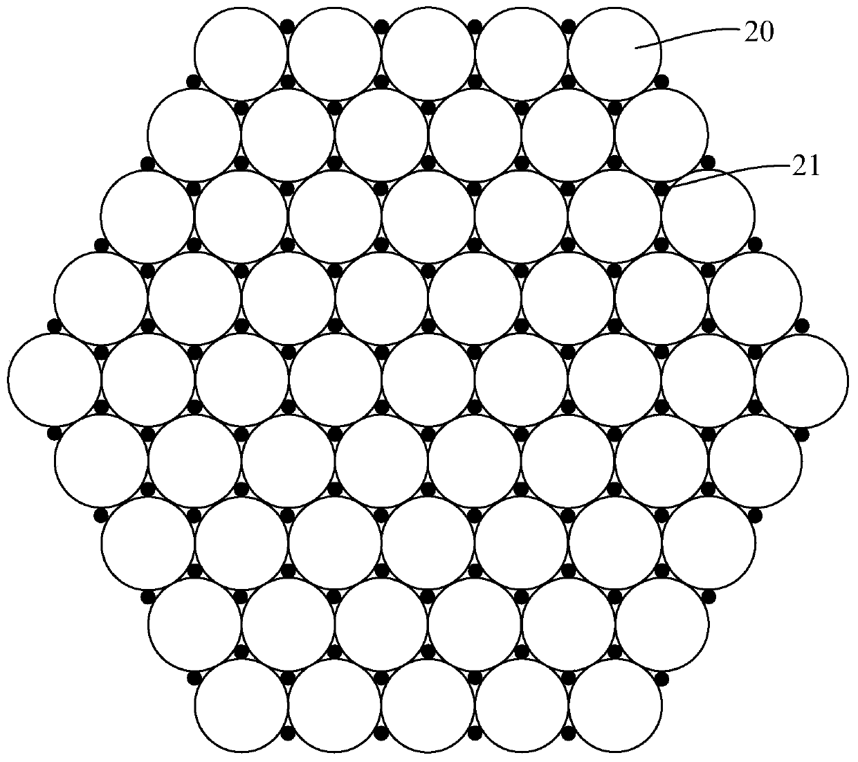
[0030] The method of inserting wires can solve the above problems to a certain extent, but the conventional solution of inserting wires leads to a decrease in the light transmittance of the fiber optic panel. Specifically, a gap is formed between the three optical fibers, and the gap is filled with a filament with a diameter about 0.14 times the diameter of the optical fiber, and the filled filament has the function of absorbing light, and the filament is called an absorbing filament; The technical solution for inserting the filaments is as follows: place absorbing filaments on all six interfaces of the optical fiber; or selectively remove some optical fiber filaments and replace them with absorbing filaments.

[0031] Such as figure 1 as shown, figure 1 It is a schematic cross-sectional structure diagram of an op...


PUM

PropertyMeasurementUnit
diameteraaaaaaaaaa
diameteraaaaaaaaaa

Abstract

The invention discloses an optical fiber panel and a debugging method thereof. The optical fiber panel comprises a plurality of optical fiber groups, white wires and absorption wires, wherein the optical fiber group comprises at least three optical fibers, the interfaces between each optical fiber and adjacent two optical fibers enclose an inner slit, the optical fiber group is internally providedwith at least one inner slit, and the interfaces between the optical fibers in each optical fiber group and the optical fibers in the adjacent optical fiber group enclose an outer slit; the white wires fill the inner slits; and the absorption wires fill the outer slits. Through special distribution of the positions and the numbers of the white wires and the absorption wires, the balance between light transmittance and image contrast is realized.

Description

technical field [0001] The invention relates to the field of optical fiber panel manufacturing, in particular to an optical fiber panel and a debugging method thereof. Background technique [0002] Fiber Optic Plate (FOP, Fiber Optical Plate) is a hard fiber optic component composed of many closely arranged optical fibers. Specifically, the optical fiber panel is formed by gathering optical fibers, cutting at an angle with the optical propagation direction, and grinding or polishing both ends to form an optical fiber panel. [0003] In the optical transmission process of the existing optical fiber panel, part of the stray light escapes from the fiber core and transmits to another optical fiber through the cladding of the optical fiber, resulting in poor image contrast. For this reason, a fiber optic faceplate using a black leather sleeve is proposed, that is, the cladding of each optical fiber is black, and the cladding is used to absorb the stray light escaping from the fi...

Claims


Application Information

Patent Timeline
Patent Type & Authority Patents(China)
IPC IPC(8): G02B6/08
Inventor 陆震生朱虹凌严
Owner SHANGHAI OXI TECH
Why Eureka
Try Eureka