Composite aircraft floor system

Inactive Publication Date: 2007-08-23
SIKORSKY AIRCRAFT
View PDF49 Cites 29 Cited by
  • Summary
  • Abstract
  • Description
  • Claims
  • Application Information

AI Technical Summary

Benefits of technology

[0011]The composite panel generally includes an inboard (non-walking surface) layer, an inboard interlock layer, a core layer, an outboard interlock layer and an outboard (walking surface) layer. The advanced sandwich core material may include K-Cor™ or X-Cor™ with composite skin materials such as, for example, carbon, fiberglass, quartz, etc. depending on the desired weight, durability and cost requirements for the floor design. The K-Cor™ material is pinned through at least one ply of dry composite reinforcement to provide a mechanical lock between the pins and an inboard and outboard interlock layer resulting in improved structural performance over standard K-Cor™ materials. Moreover, damage tolerance of the flo

Problems solved by technology

High speed machined floor designs require less tooling and have higher tolerances, but may not achieve the weight benefits of composite floor systems.
Although composite floor systems are generally lighter in weight than metallic floors, composite floor systems may be more expensive and labor intensive to manufacture compared to metallic floor systems.
Current composite floor system floor panels may require relatively complicated and labor intensive process steps including: pre-curing of the inboard and outboard skins; cutting, machining, and forming of the honeycomb core; local densification of the honeycomb core at attachment hard points and edge closeouts; preparati

Method used


Image

  • Composite aircraft floor system
  • Composite aircraft floor system
  • Composite aircraft floor system

Examples


Example

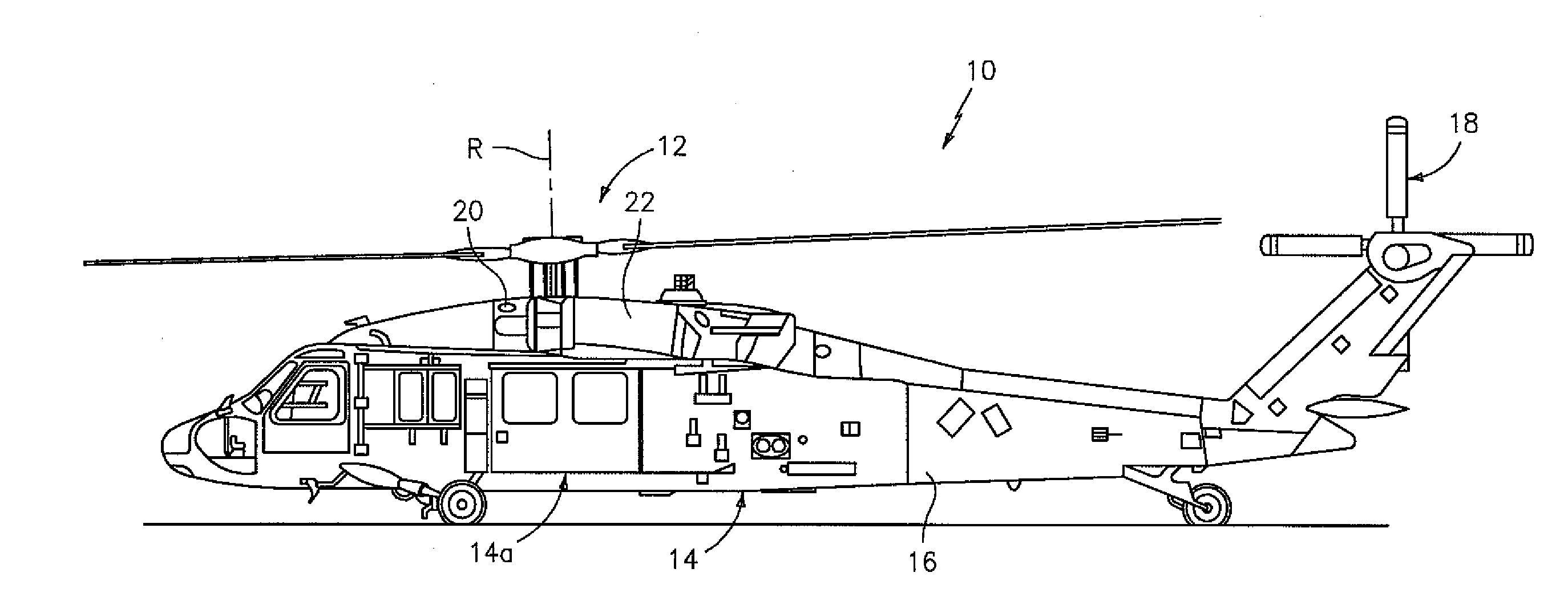
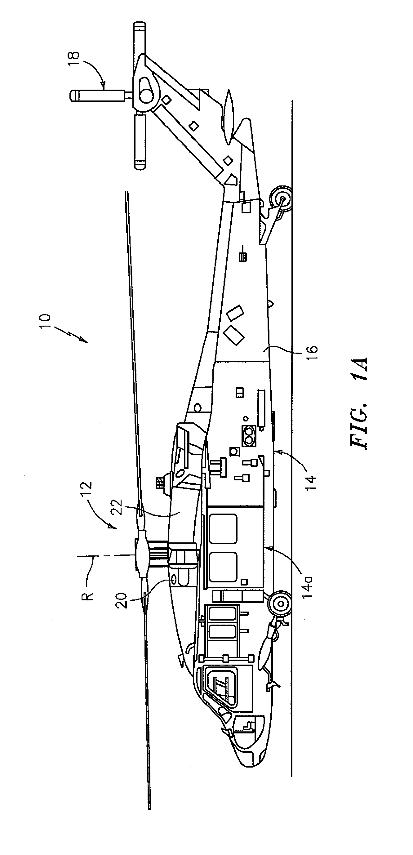
[0032]FIG. 1A schematically illustrates a rotary-wing aircraft 10 having a main rotor system 12. The aircraft 10 includes an airframe 14 having an extending tail 16 which mounts a tail rotor system 18, such as an anti-torque system. The airframe 14 includes an airframe section 14A. The main rotor assembly 12 is driven about an axis of rotation R through a main gearbox (illustrated schematically at 20) by one or more engines 22. The main rotor system 12 includes a multiple of rotor blades mounted to a rotor hub. Although a particular helicopter configuration is illustrated and described in the disclosed embodiment, other configurations and / or machines, such as high speed compound rotary wing aircraft with supplemental translational thrust systems, dual contra-rotating, coaxial rotor system aircraft, turbo-props, tilt-rotors and tilt-wing aircraft, will also benefit from the present invention.

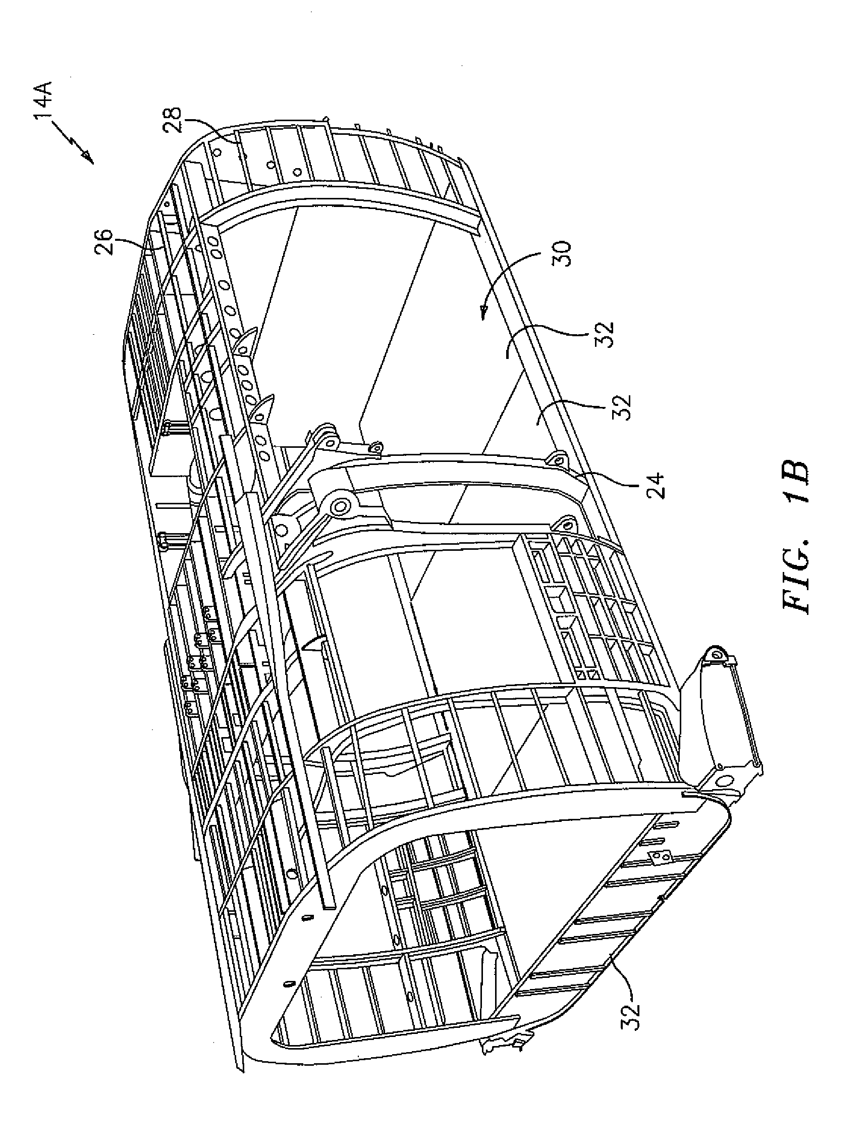
[0033]Referring to FIG. 1B, the airframe section 14A, here illustrated as a cabin section, wh...


PUM


Abstract

An aircraft floor system includes a composite panel which generally includes an inboard layer, an inboard interlock layer, a core layer, an outboard interlock layer and an outboard layer. The advanced sandwich core material may include K-Cor™ or X-Cor™ which is pinned through at least one ply of dry composite reinforcement to provide a mechanical lock between the pins and an inboard and outboard interlock layer. Bonding of the locked-in ply with the inboard and outboard results in improved structural performance and damage tolerance.

Description

[0001]The present application claims priority to U.S. Provisional Patent Application Ser. No. 60 / 764,047, filed Jan. 31, 2006.[0002]This invention was made with government support under Contract No.: DAHH10-03-2-0003, awarded by the Department of Army. The government therefore has certain rights in this invention.BACKGROUND OF THE INVENTION[0003]The present invention relates to an aircraft floor system, and more particularly to a lightweight floor panel with an advanced sandwich core structure with a mechanical interlock.[0004]Current aircraft floor systems incorporate thin metallic or composite prepreg skin materials adhesively bonded to either a metallic or non-metallic honeycomb core. Recent improvements in machining technology have lead to the use of high speed machined aluminum floor designs for rotary-wing aircraft. High speed machined floor designs require less tooling and have higher tolerances, but may not achieve the weight benefits of composite floor systems.[0005]Althoug...

Claims


Application Information

Patent Timeline
IPC IPC(8): E04B1/00
CPCY02T50/46Y10T428/24289B64D9/003B64C1/20Y10T428/249923Y02T50/40
Inventor CARSTENSEN, THOMAS A.COURNOYER, DAVID M.URSENBACH, DAN
Owner SIKORSKY AIRCRAFT
Why Eureka
Try Eureka