Composite landing gear apparatus and methods

a landing gear and composite technology, applied in the field of composite structures, can solve the problems of prior art composite components being unsuitable, unable to provide other desirable properties, and composite components may fail to provide flexibility, so as to improve structural performance, reduce weight, and improve the effect of structural performan

Active Publication Date: 2006-12-21
THE BOEING CO
View PDF69 Cites 31 Cited by
  • Summary
  • Abstract
  • Description
  • Claims
  • Application Information

AI Technical Summary

Benefits of technology

[0004] The present invention is directed to composite landing gear apparatus and methods, including composite landing gear for manned and unmanned aerial vehicles. Embodiments of apparatus and methods in accordance with the present invention may advantageously provide landing gear assemblies having significantly enhanced structural performance, substantially reduced weight, and substantially reduced cost, in comparison with prior art landing assemblies

Problems solved by technology

For example, although composite components may provide the desired strength characteristics, under some circumstances, such composite components may fail to provide other desirable properties, including flexibility.
Therefore, for some applications, prior art composite components may be unsuitable despite their desirable weight and strength characteristics.

Method used


Image

  • Composite landing gear apparatus and methods
  • Composite landing gear apparatus and methods
  • Composite landing gear apparatus and methods

Examples


Embodiment Construction

[0015] The present invention relates to composite landing gear apparatus and methods, including composite landing gear for unmanned aerial vehicles. Many specific details of certain embodiments of the invention are set forth in the following description and in FIGS. 1-8 to provide a thorough understanding of such embodiments. The present invention may have additional embodiments, or may be practiced without one or more of the details described for any particular described embodiment.

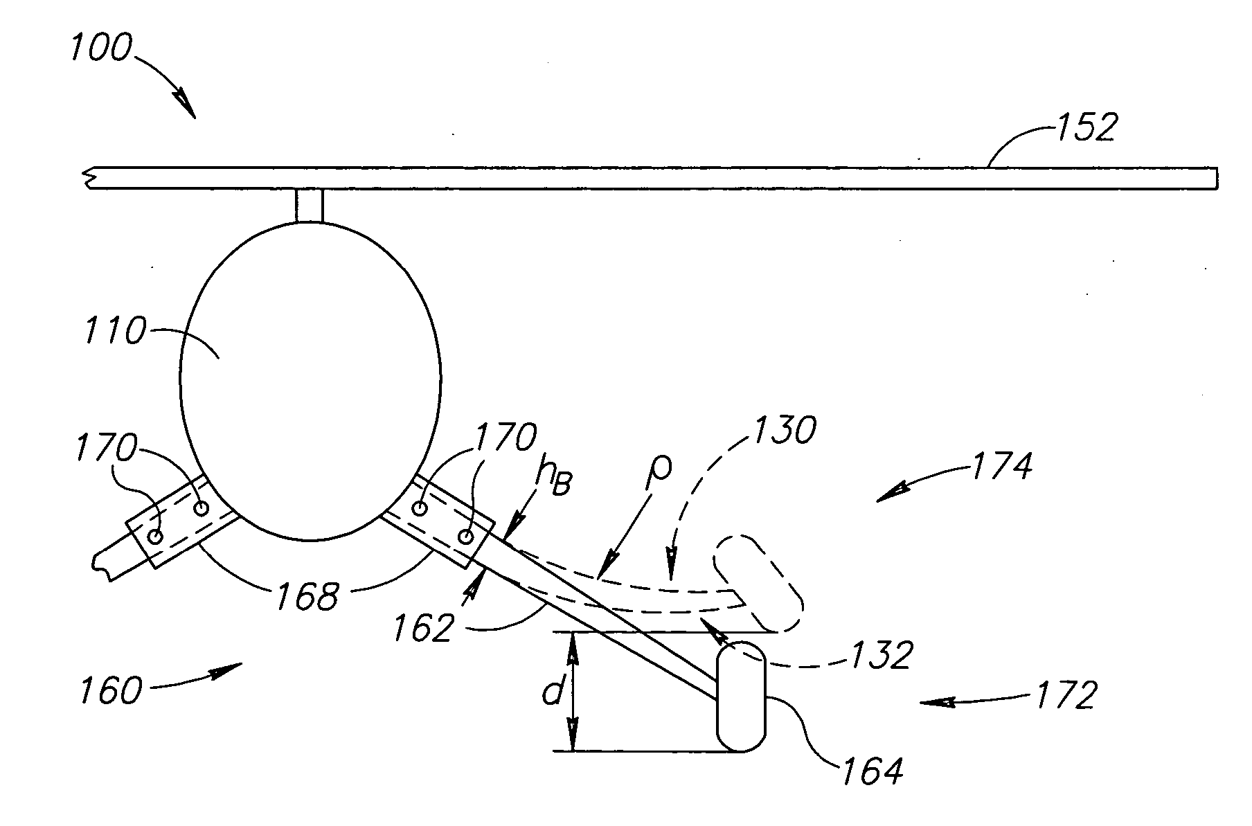
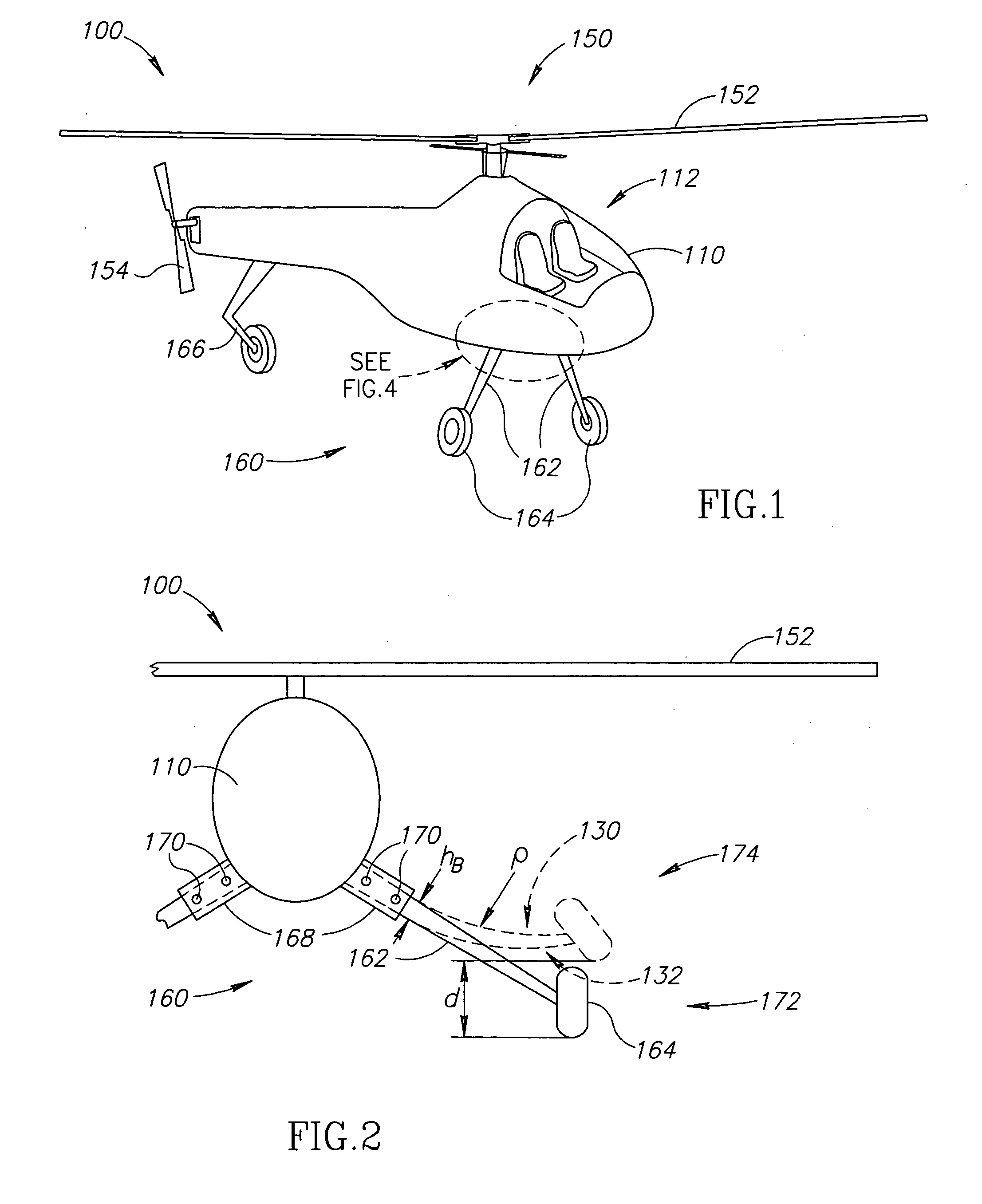
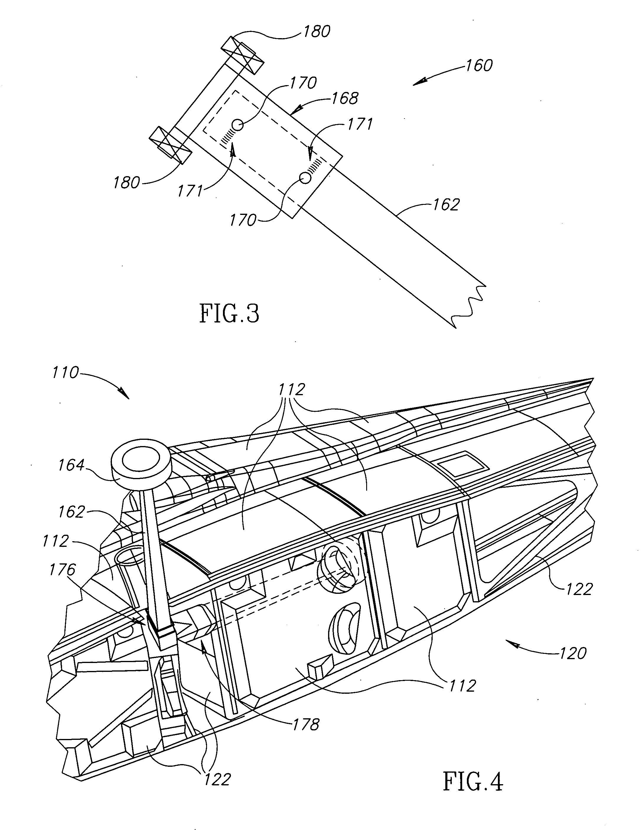
[0016]FIG. 1 is an isometric view of an aircraft 100 in accordance with an embodiment of the invention. In this embodiment, the aircraft 100 includes a fuselage 110 and a rotary lift and propulsion system 150 having a main rotor 152 and a tail rotor 154. A landing gear assembly 160 projects outwardly from the fuselage 110 and includes a pair of composite legs 162. A landing wheel 164 is operatively coupled to each composite leg 162 and a tail landing gear 166 projects downwardly from an aft portion of t...


PUM


Abstract

Composite landing gear apparatus and methods are disclosed. In one embodiment, a composite component includes an elongated member having a first composite portion coupled to a second composite portion by a pair of composite sidewall portions and forming an elongated cavity therebetween. The first composite portion includes a plurality of first layers, each first layer having a plurality of first fibers disposed therein. Similarly, the second composite portion includes a plurality of second layers, each second layer having a plurality of second fibers disposed therein. The first and second fibers are oriented substantially parallel to a longitudinal axis of the elongated cavity. The composite sidewall portions include a plurality of third layers each third layer having a plurality of third fibers disposed therein, the third fibers being cross-woven and non-parallel with the longitudinal axis.

Description

FIELD OF THE INVENTION [0001] This invention relates to composite structures, and more specifically, to composite landing gear apparatus and methods, including composite landing gear for manned and unmanned aerial vehicles, both fixed wing and rotary lift systems. BACKGROUND OF THE INVENTION [0002] Composite components are being utilized in a wide variety of articles of manufacture due to their high strength and lightweight. This is particularly true in the field of aircraft manufacturing. Typical materials used in the manufacture of composite components include glass or graphite fibers that are embedded in resins, such as phenolic, epoxy, and bismaleimide resins. The fiber and resin materials may be formed into a desired shape using a variety of different manufacturing systems and processes, and may then be cured (e.g. under elevated pressure and temperature conditions) to produce the desired component. [0003] Although desirable results have been achieved, there is room for improve...

Claims


Application Information

Patent Timeline
Patent Type & Authority Applications(United States)
IPC IPC(8): B64C25/58
CPCB64C2025/325B64C25/10
Inventor KISMARTON, MAX U.
Owner THE BOEING CO
Why Eureka
Try Eureka