
Optical backplane system, switching system and upgrading method of switching system

A technology of optical backplane and level light, applied in the field of communication, can solve problems such as business interruption, and achieve the effect of improving work efficiency

Active Publication Date: 2019-06-04
HUAWEI TECH CO LTD
View PDF5 Cites 3 Cited by
  • Summary
  • Abstract
  • Description
  • Claims
  • Application Information

AI Technical Summary

Problems solved by technology

[0004] In order to solve the problem that the business of the entire optical backplane or even the entire cabinet needs to be interrupted during the upgrading process of the optical backplane, this application provides an optical backplane system, a switching system and an upgrading method thereof

Method used


Image

  • Optical backplane system, switching system and upgrading method of switching system
  • Optical backplane system, switching system and upgrading method of switching system
  • Optical backplane system, switching system and upgrading method of switching system

Examples


Embodiment Construction

[0057] In order to make the purpose, technical solution and advantages of the present application clearer, the implementation manners of the present application will be further described in detail below in conjunction with the accompanying drawings.

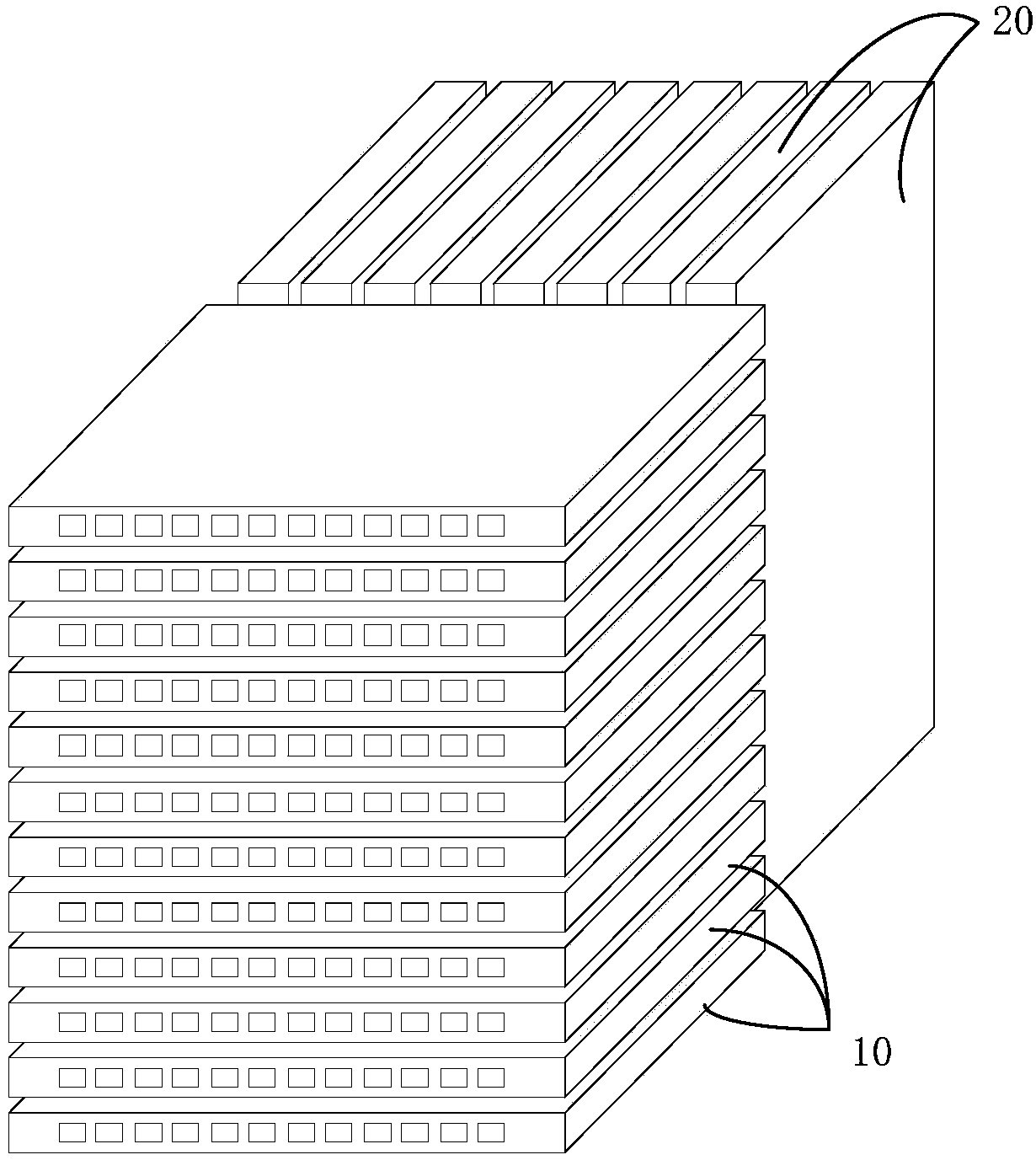
[0058] An embodiment of the present invention provides an optical backplane system, Figure 1a It is a schematic structural diagram of an optical backplane system provided by an embodiment of the present invention. Such as Figure 1a As shown, the optical backplane system includes multiple front-level optical interconnection modules 10 and multiple rear-level optical interconnection modules 20 . Multiple front-level optical interconnection modules 10 and multiple subsequent-level optical interconnection modules 20 are connected to each other.

[0059] The following uses the first pre-stage optical interconnection module, the first post-stage optical interconnection module, and the second post-stage optical interconnection module ...


PUM


Abstract

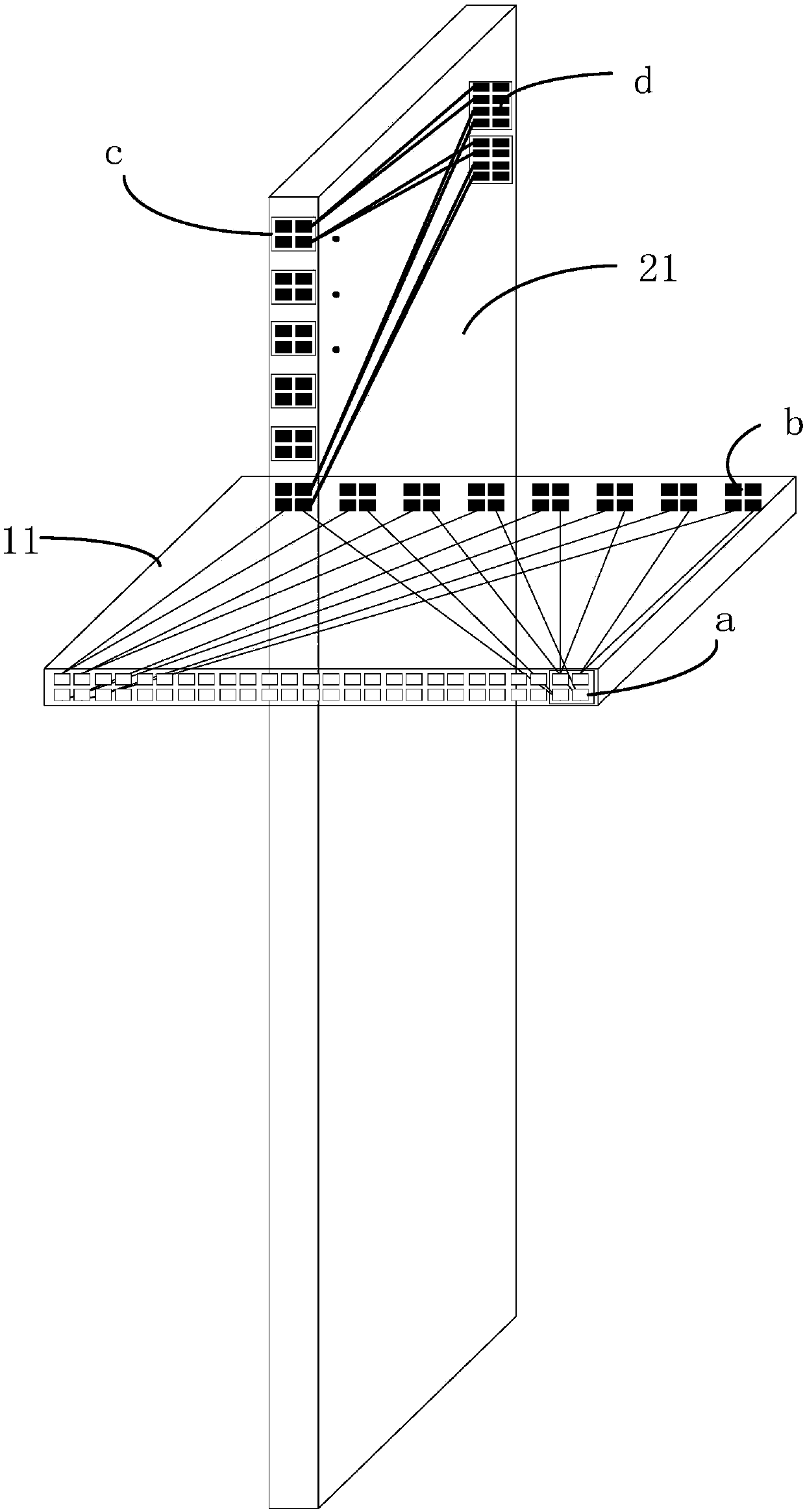
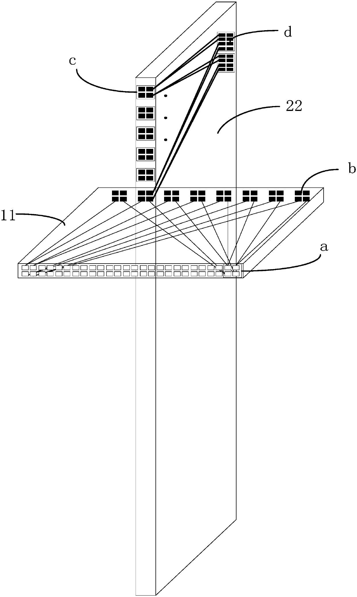
The invention discloses an optical backboard system, a switching system and an upgrading method of the switching system. The optical backboard system comprises a first pre-stage optical interconnection module, a first post-stage optical interconnection module and a second post-stage optical interconnection module. Wherein the first pre-stage optical interconnection module comprises M1 first interfaces and N1 second interfaces which have a connection relationship; The first post-stage optical interconnection module comprises L1 third interfaces and K1 fourth interfaces which have a connection relationship; The second post-stage optical interconnection module comprises L2 third interfaces and K2 fourth interfaces which have a connection relationship; The first pre-stage optical interconnection module is connected with one of L1 third interfaces of the first post-stage optical interconnection module through one of N1 second interfaces; The first pre-stage optical interconnection module isconnected with one of the L2 third interfaces of the second post-stage optical interconnection module through the other second interface of the N1 second interfaces; The first interface and the fourth interface are used for being connected with a processing module, and M1, N1, K1, K2, L1 and L2 are all larger than 1.

Description

technical field [0001] The invention relates to the technical field of communication, in particular to an optical backplane system, a switching system and an upgrading method thereof. Background technique [0002] The backplane is an important part of the network switching equipment, and its main function is to realize the cross-connection between the line processing unit and the switching network unit. According to the different transmission media used, the backplane can be divided into optical backplane and electric backplane. For these two backplanes, the optical backplane can achieve higher system capacity, so it is widely used. [0003] The optical backplane usually includes a carrier board and a plurality of line processing unit slots arranged on the carrier board. Each line processing unit slot is connected to the switching network unit through a certain number of optical channels. If the number of optical channels on the optical backplane is insufficient, you need...

Claims


Application Information

Patent Timeline
IPC IPC(8): H04B10/40H04B10/25H04L12/931
CPCH04B10/801G02B6/43H04Q11/0005H04Q2011/0052
Inventor 莫道春刘庆智徐小飞雷文阳王闯王临春
Owner HUAWEI TECH CO LTD
Learn More