Solenoid valve for controlling the brake pressure of a wheel brake

A wheel brake and brake pressure technology, which is applied in the direction of brakes, control valves, air release valves, brake components, etc., can solve problems such as pressure adjustment fluctuations, skewed contact surfaces, and influence on pressure adjustment accuracy, and achieve uniform force flow, Avoid the effect of tilting

Active Publication Date: 2019-06-04
ROBERT BOSCH GMBH
View PDF8 Cites 3 Cited by
  • Summary
  • Abstract
  • Description
  • Claims
  • Application Information

AI Technical Summary

Problems solved by technology

This results in a certain degree of skewing of the contact surface also at the rear (armature-facing) end of the valve element
The resulting component inaccuracies (especially inaccuracies at the armature, valve elements) can very strongly affect the pressure regulation accuracy
[0006] In addition, different component orientations can occur between the armature and the pushrod, which can lead to fluctuations in pressure regulation (e.g. figure 2 shown), since various positions between the armature and pushrod can be adjusted and thus produce different magnetic forces

Method used


Image

  • Solenoid valve for controlling the brake pressure of a wheel brake
  • Solenoid valve for controlling the brake pressure of a wheel brake
  • Solenoid valve for controlling the brake pressure of a wheel brake

Examples


Embodiment Construction

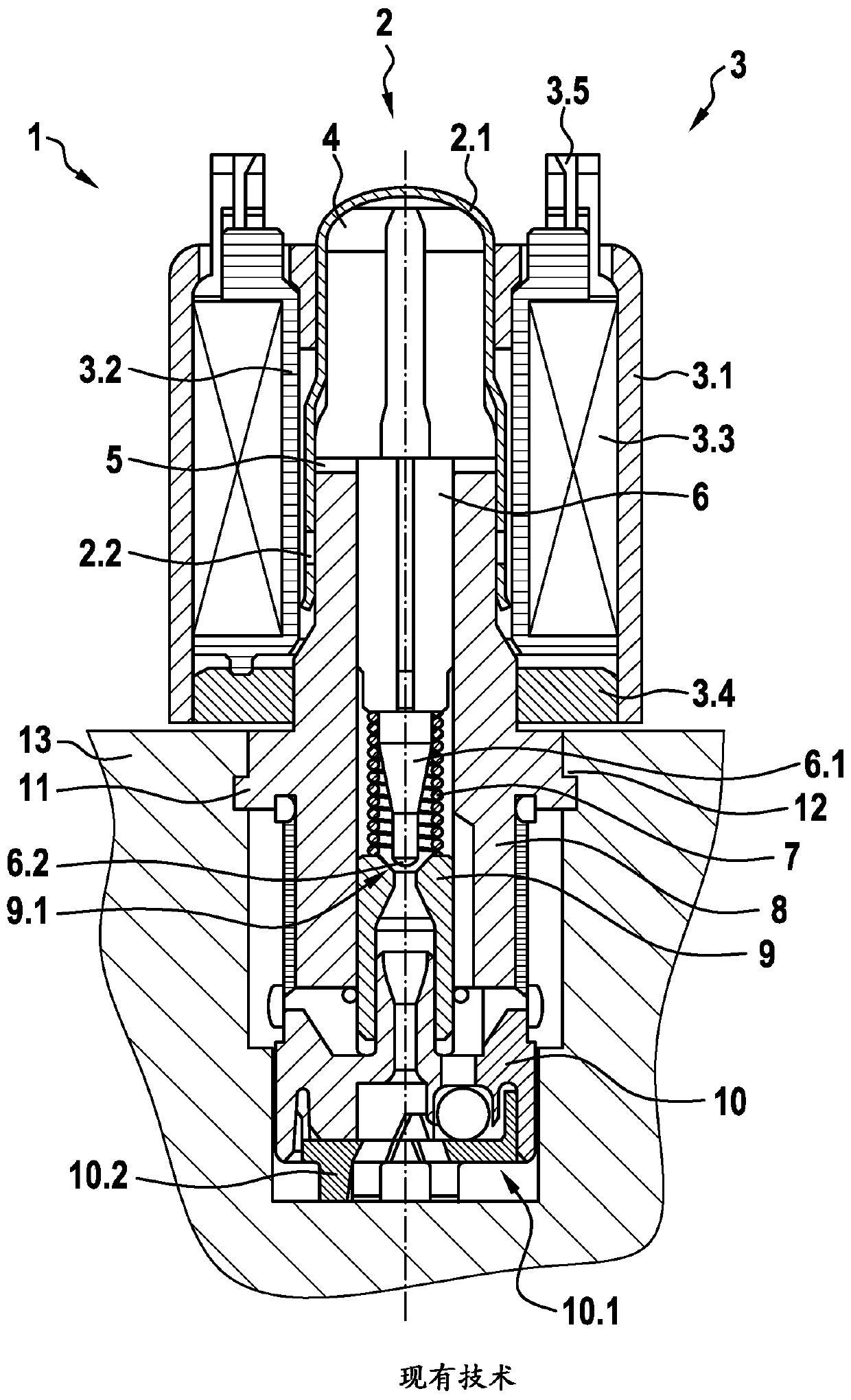
[0054] exist figure 1 A schematic cross-sectional view of a conventional solenoid valve is shown in . This has been described as prior art.

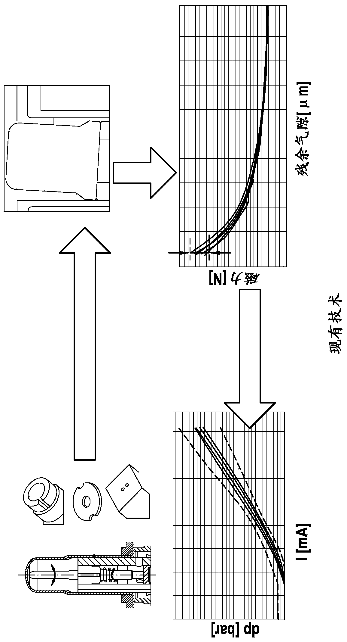
[0055] figure 2 The causal chain is also shown schematically. In this case, possible inaccuracies in the individual components are shown in the illustration in the upper left corner. One of these inaccuracies is the deformation of the valve components depending on the material and manufacturing. For example, such inaccuracies may lead to tipping or tipping of the armature relative to the valve insert. This is shown in the upper right corner of the drawing. Rotation of the armature and / or valve element results when the valve is used. This results in a varying tilted position of the armature, for example with respect to the valve seat. However, a varying tilted position of the armature results in a varying magnetic force acting on the armature. This is shown in the attached image on the bottom right. The varying magnetic force ac...


PUM


Abstract

The invention relates to a solenoid valve for controlling the brake pressure of a wheel brake of a slip-regulatable hydraulic brake system of a motor vehicle. The solenoid valve includes a valve element which is arranged at least partly in a valve insert in a longitudinally movable manner and interacts with a valve seat and which is acted upon by a force component acting in the opening direction with respect to the valve seat by means of a spring device in the assembled position and can be actuated by means of an electromagnetic actuator in the closing direction with respect to the valve seat.The valve element is arranged between an armature and the valve seat, and the valve element is equipped with a contact surface on which the valve element is operatively connected to the armature. Thesolenoid valve is characterized in that the contact surface is designed such that a non-rectangular intersection angle is formed between the central axis of the valve element and the contact surface.

Description

technical field [0001] The invention relates to a solenoid valve for controlling the brake pressure of a slip-controlled hydraulic brake system of a wheel brake of a motor vehicle, which has a longitudinally displaceable manner at least partially arranged in a valve insert and in an installed position The spring device is loaded with a force component acting in the opening direction relative to the valve seat and is actuated in the closing direction relative to the valve seat by the electromagnetic actuator. Therein, the valve element is arranged between the armature and the valve seat and a contact surface is formed on the valve element on which the valve element is operatively connected to the armature, characterized in that the contact surface is formed such that at the valve element There is a non-right angle between the central axis and the contact surface. Background technique [0002] For example, patent application DE 10 2007 053 134 A1 is known from the prior art. ...

Claims


Application Information

Patent Timeline
Patent Type & Authority Applications(China)
IPC IPC(8): B60T8/36
CPCB60T8/363B60T13/686G05D16/2022B60T8/341B60T15/028B60T2270/10F16K31/0651
Inventor M·埃特勒S·施泰因加斯C·博德曼H-P·巴托施S·科纳科特P·穆勒
Owner ROBERT BOSCH GMBH
Why Eureka
Try Eureka