

A visual magnetic separation method
A magnetic separation and magnet technology, applied in the field of magnetic separation, can solve the problems of inability to accurately judge the end time of magnetic separation, inability to determine the correct relationship between the length of the channel system and magnetic separation, etc., to reduce losses, reduce costs, and widely applicable. Effect
- Summary
- Abstract
- Description
- Claims
- Application Information
AI Technical Summary
Problems solved by technology
Method used
Image

Examples
Embodiment 1
[0031] like figure 1 As shown, a visual magnetic separation method, the specific steps are as follows:
[0032] Preparation of S1 solution: Mix target solution 1 with a solution containing magnetic particles to obtain a mixed solution, and place the mixed solution in a transparent container;
[0033] Preparation of the S2 magnetic field: Take the cylinder as the magnetic frame, set an annular interlayer on the side wall of the cylinder, and set a magnet in the interlayer, and place the transparent container for the mixed solution in S1 in the cylinder;
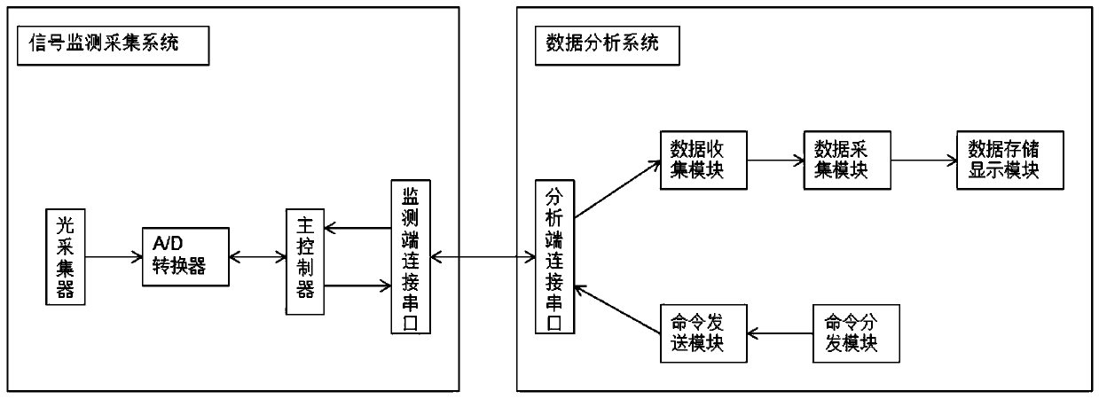
[0034] Monitoring and collection of S3 signal: A signal monitoring and collection system is installed in the cylinder in S2. The signal monitoring and collection system includes an optical collector, an A / D converter, a main controller and a serial port connected to the monitoring terminal, which are electrically connected in sequence. The end connection serial port is set on the surface of the cylinder. Specifically, the lig...
Embodiment 2
[0044] like figure 1 As shown, a visual magnetic separation method, the specific steps are as follows:
[0045] Preparation of S1 solution: Mix the target solution 1 with the same solute as in Example 1 with the solution containing magnetic particles to obtain a mixed solution, and place the mixed solution in a transparent container;
[0046] Preparation of the S2 magnetic field: Take the cylinder as the magnetic frame, set an annular interlayer on the side wall of the cylinder, and set a magnet in the interlayer, and place the transparent container for the mixed solution in S1 in the cylinder;
[0047] Monitoring and collection of S3 signal: A signal monitoring and collection system is installed in the cylinder in S2. The signal monitoring and collection system includes an optical collector, an A / D converter, a main controller and a serial port connected to the monitoring terminal, which are electrically connected in sequence. The end connection serial port is set on the sur...
Embodiment 3
[0056] like figure 1 As shown, a visual magnetic separation method, the specific steps are as follows:
[0057] Preparation of S1 solution: mix the target solution with solution 3 containing magnetic particles to obtain a mixed solution, and place the mixed solution in a transparent container;
[0058] Preparation of the S2 magnetic field: Take the cylinder as the magnetic frame, set an annular interlayer on the side wall of the cylinder, and set a magnet in the interlayer, and place the transparent container for the mixed solution in S1 in the cylinder;
[0059] Monitoring and collection of S3 signal: A signal monitoring and collection system is installed in the cylinder in S2. The signal monitoring and collection system includes an optical collector, an A / D converter, a main controller and a serial port connected to the monitoring terminal, which are electrically connected in sequence. The end connection serial port is set on the surface of the cylinder. Specifically, the l...
PUM
 Abstract
Description
Claims
Application Information