Brush roller for silk fabric printing and dyeing machine

A brush roller and printing and dyeing machine technology, which is applied in the brush field of silk fabric printing and dyeing machines, can solve the problems of low replacement efficiency, uneven washing of silk fabrics, and reduce the efficiency of replacing several brush strips, and achieve high replacement efficiency

Inactive Publication Date: 2019-06-07
湖州飞顺丝绸有限公司
View PDF0 Cites 3 Cited by
  • Summary
  • Abstract
  • Description
  • Claims
  • Application Information

AI Technical Summary

Problems solved by technology

The brush roller used in the existing silk fabric printing and dyeing machine consists of a brush roller body (i.e. a brush roller) and some brush strips evenly distributed on the periphery of the brush roller body. Bristles, because the brush roller used in the existing silk fabric printing and dyeing machine causes some bristles to be damaged due to scrubbing high-density silk fabrics, there is a problem that the silk fabrics are not evenly scrubbed and cannot meet the requirements of silk fabric scrubbing, so it is necessary to replace the damaged part of the bristles, and Because some bristles are planted on the brush strips and cannot be disassembled, it is necessary to replace some brush strips where the damaged part of the bristles are located, and also because several brush strips are fixed on the outer circular wall of the brush roller body by multiple sets of screws , so the time to replace several brush strips is increased, thereby reducing the efficiency of replacing several brush strips
[0003] Therefore, the brush roller used in the existing silk fabric printing and dyeing machine has the problem of low replacement efficiency when part of the bristles are damaged.

Method used


Image

  • Brush roller for silk fabric printing and dyeing machine
  • Brush roller for silk fabric printing and dyeing machine
  • Brush roller for silk fabric printing and dyeing machine

Examples


Embodiment Construction

[0017] The present invention will be further described below in conjunction with the accompanying drawings and embodiments, but not as a basis for limiting the present invention.

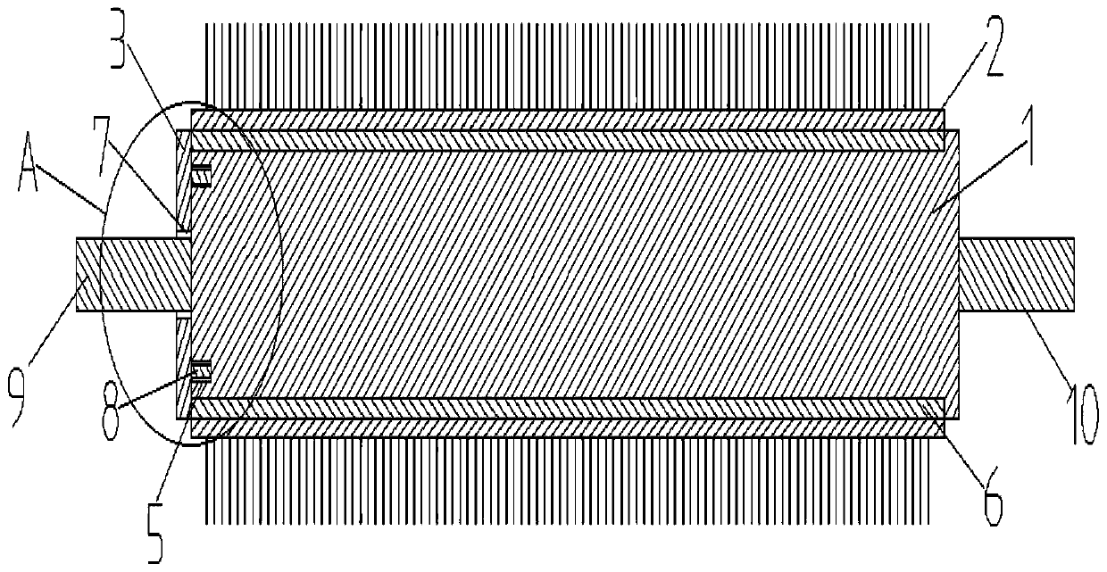
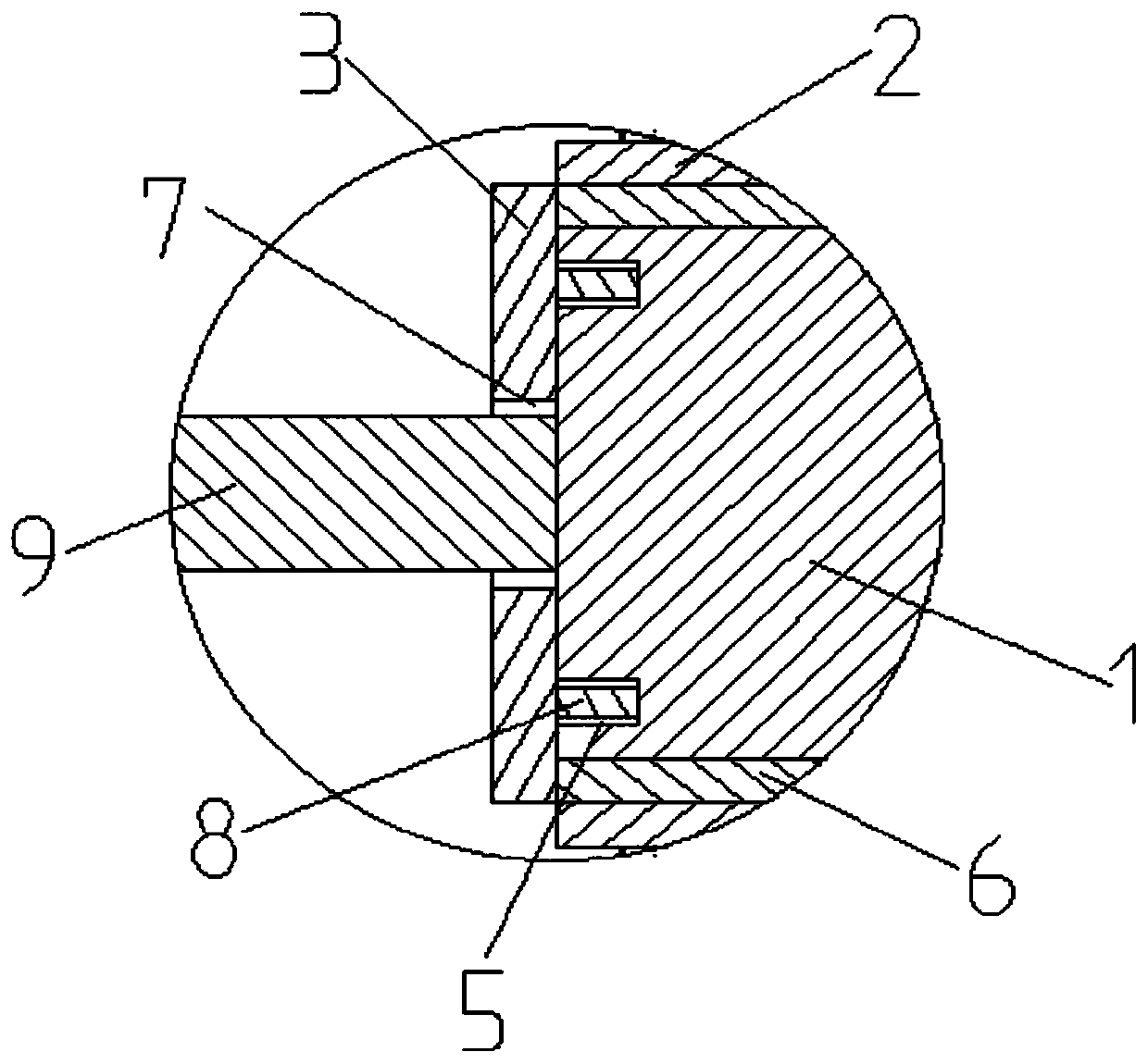
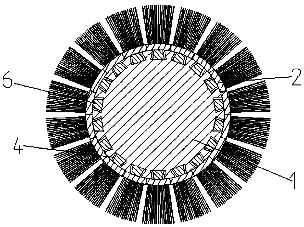
[0018] Example. A brush roller for a silk fabric printing and dyeing machine, consisting of Figure 1-4 As shown, the brush roller body 1 is a brush roller of the prior art, and the periphery of the brush roller body 1 is evenly distributed with some first brush strips 2, and one end of the brush roller body 1 is connected with a brush cover 3; One end of the brush roller body 1 connected to the brush cover 3 is provided with a first roller shaft 9 and several draw-in grooves 5, and the other end of the brush roller body 1 is provided with a second roller shaft 10, and the brush roller body 1 Several transverse dovetail grooves 4 are evenly distributed on the outer circular wall, and some transverse dovetail grooves 4 are dovetail grooves with one end sealed, and the sealing ends of several transve...


PUM

PropertyMeasurementUnit
Bottom corneraaaaaaaaaa

Abstract

The invention discloses a brush roller for a silk printing and dyeing machine, which comprises a brush roller body (1), wherein a plurality of first brush strips (2) are uniformly distributed on the periphery of the brush roller body (1), and one end of the brush roller body (1) is connected with a brush cover (3) ; one end of the brush roller body (1) connected with the brush cover (3) is provided with a first roller shaft (9) and a plurality of clamping grooves (5), the other end of the brush roller body (1) is provided with a second roller shaft (10), a plurality of transverse dovetail grooves (4) are uniformly distributed on the excircle wall of the brush roller body (1), the transverse dovetail grooves (4) are dovetail grooves with one end sealed, and the sealing ends of the transverse dovetail grooves (4) are arranged on the excircle wall of the brush roller body (1) ; transverse dovetail tenons (6) are arranged on the inner circular arc walls of the first brush strips (2), and the transverse dovetail tenons (6) are correspondingly connected with the transverse dovetail grooves (4). The brush roller for silk fabric pringting and dyeing machine has the advantage of higher replacement efficiency when part of the bristles is damaged.

Description

technical field [0001] The invention relates to the technical field of brushes for silk fabric printing and dyeing machines, in particular to a brush roller for silk fabric printing and dyeing machines. Background technique [0002] The brush roller for silk fabric printing and dyeing machine is used for scrubbing silk fabrics. The brush roller used in the existing silk fabric printing and dyeing machine consists of a brush roller body (i.e. a brush roller) and some brush strips evenly distributed on the periphery of the brush roller body. Bristles, because the brush roller used in the existing silk fabric printing and dyeing machine causes some bristles to be damaged due to scrubbing high-density silk fabrics, there is a problem that the silk fabrics are not evenly scrubbed and cannot meet the requirements of silk fabric scrubbing, so it is necessary to replace the damaged part of the bristles, and Because some bristles are planted on the brush strips and cannot be disasse...

Claims


Application Information

Patent Timeline
IPC IPC(8): A46B7/04D06B23/02
Inventor 姚红根
Owner 湖州飞顺丝绸有限公司
Why Eureka
Try Eureka