Building or structure with multifunctional rope releasing device

A multi-functional, structural technology, applied in life-saving equipment, building rescue, fire rescue, etc., can solve the problems of incomplete fire-fighting facilities, complex structure, blocking with debris, etc.

Inactive Publication Date: 2019-06-07
福州市晋安区澳榕自动化设备有限公司
View PDF0 Cites 0 Cited by
  • Summary
  • Abstract
  • Description
  • Claims
  • Application Information

AI Technical Summary

Problems solved by technology

[0002] Fires in high-rise buildings or structures have always drawn people's attention. In the event of a fire, the reliability of fire elevators is worth pondering. There is also an arm-raising fire truck used in existing firefighting and lifesaving, which can generally implement fire fighting and rescue at a height of 53 meters. Rescue people, and there is a limit to the height of the fire-fighting aerial ladder truck. Usually, the fire-fighting aerial ladder truck can only rise to about 80% of the limit value. Once the above-mentioned high-rise buildings or structures catch fire or people are trapped, it is difficult for the fire ladder to play a role. Generally, the trapped people can only rely on their own ability to escape, but some high-rise buildings or structures have incomplete fire-fighting facilities, and the existence of fire hy...

Method used


Image

  • Building or structure with multifunctional rope releasing device
  • Building or structure with multifunctional rope releasing device
  • Building or structure with multifunctional rope releasing device

Examples


Embodiment Construction

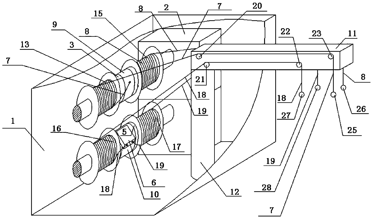
[0076] Such as figure 1 as shown, figure 1 It is a schematic oblique view of the multifunctional rope releasing device according to the first embodiment of the present application. The multifunctional rope-releasing device includes a housing 1, an electric motor 2, a rotating shaft 3, a rotating shaft 5, a descending device 6, a pull rope 7, a pull rope 8, a rotating ring body 9, a rotating ring body 10, a cantilever 11, and a column 12 , the above-mentioned electric motor 2, rotating shaft 3, rotating shaft 5, slow descender 6, stay rope 7, stay rope 8, rotating ring body 9, rotating ring body 10, column 12 are arranged in the housing, electric motor 2 and rotating shaft 3, rotating shaft The 5 connection can drive the rotating shaft 3 and the rotating shaft 5 to rotate. The above-mentioned rotating ring body 9 is sleeved on the outer circumference of the rotating shaft 3 and can rotate around the rotating shaft 3. The above-mentioned rotating ring body 10 is sleeved on the ...


PUM


Abstract

The invention provides a building or structure with a multifunctional rope releasing device. The multifunctional rope releasing device is arranged on the roof of the building and comprises an electrictransmission system or a hydraulic transmission system or a pneumatic transmission system, winding drums or rotating shafts and pull ropes. Rotation shafts of motors of the electric transmission system or the hydraulic transmission system or the pneumatic transmission system can drive the winding drums or the rotating shafts to rotate. Rotation ring bodies are connected to winding drum shafts ofthe winding drums mentioned above or the rotating shafts mentioned above. Each rotation ring body mentioned above can only rotate in one direction and is locked and cannot rotate in the other direction. The pull ropes mentioned above are connected to the rotation ring bodies. The pull ropes mentioned above are wound around the winding drums or the rotating shafts and extend out from the winding drums or the rotating shafts after extending out from the rotation ring bodies. A cable connected with an electric motor extends downwards to the lower portion or the outer portion of the building and is connected with a power supply through a main contact of a contactor. A coil of the contactor mentioned above is connected with a PLC and the power supply to form a loop.

Description

technical field [0001] The application belongs to a building or structure with functions of fire extinguishing, rescue and escape. Background technique [0002] Fires in high-rise buildings or structures have always drawn people's attention. In the event of a fire, the reliability of fire elevators is worth pondering. There is also an arm-raising fire truck used in existing firefighting and lifesaving, which can generally implement fire fighting and rescue at a height of 53 meters. Rescue people, and there is a limit to the height of the fire-fighting aerial ladder truck. Usually, the fire-fighting aerial ladder truck can only rise to about 80% of the limit value. Once the above-mentioned high-rise buildings or structures catch fire or people are trapped, it is difficult for the fire ladder to play a role. Generally, the trapped people can only rely on their own ability to escape, but some high-rise buildings or structures have incomplete fire-fighting facilities, and the ex...

Claims


Application Information

Patent Timeline
IPC IPC(8): A62B1/10A62B1/12A62B1/18A62C31/00
Inventor 不公告发明人
Owner 福州市晋安区澳榕自动化设备有限公司
Why Eureka
Try Eureka