
Low clearance rotary adjustable supporting suspension wire clamp

A technology of hanging wire clips and low headroom, which is applied in the direction of overhead lines, etc., can solve the problems that the wire clips do not have rotation and up and down adjustment, the connecting shaft cannot be fixed, and the wire clip clearance requirements are high, so as to improve safety and stability, and the adjustment is simple and convenient , the effect of strong versatility of tools

Pending Publication Date: 2019-06-07
CHINA RAILWAY HIGH SPEED ELECTRIFICATION EQUIP CORP LTD
View PDF0 Cites 0 Cited by
  • Summary
  • Abstract
  • Description
  • Claims
  • Application Information

AI Technical Summary

Problems solved by technology

[0003] The invention provides a low-clearance adjustable support suspension clamp, which solves the problem of high clearance requirements for the clamp in the rigid suspension system of the existing electrified railway, many fastening bolts, inconvenient installation, inability to fix the connecting shaft, low performance stability, and safety. The problem of large hidden dangers solves the problem that the clamps in the rigid suspension system of urban rail transit do not have the functions of rotation and up and down adjustment, and are suitable for low clearance tunnels, with stable structure, convenient installation and adjustment

Method used


Image

  • Low clearance rotary adjustable supporting suspension wire clamp
  • Low clearance rotary adjustable supporting suspension wire clamp
  • Low clearance rotary adjustable supporting suspension wire clamp

Examples


Embodiment Construction

[0022] The structure of the suspension clamp is specifically described below in combination with the bracket for installing the suspension clamp:

[0023] Such as Figure 7 and Figure 8 The adjustment bracket A in the catenary support device shown is provided with a limit groove B and a guide groove C, and the limit groove B and the guide groove C are arranged along the length direction of the adjustment bracket A, so that the suspension wire clip installed on the adjustment bracket A along the Position adjustment can be realized by adjusting the length direction of the bracket A.

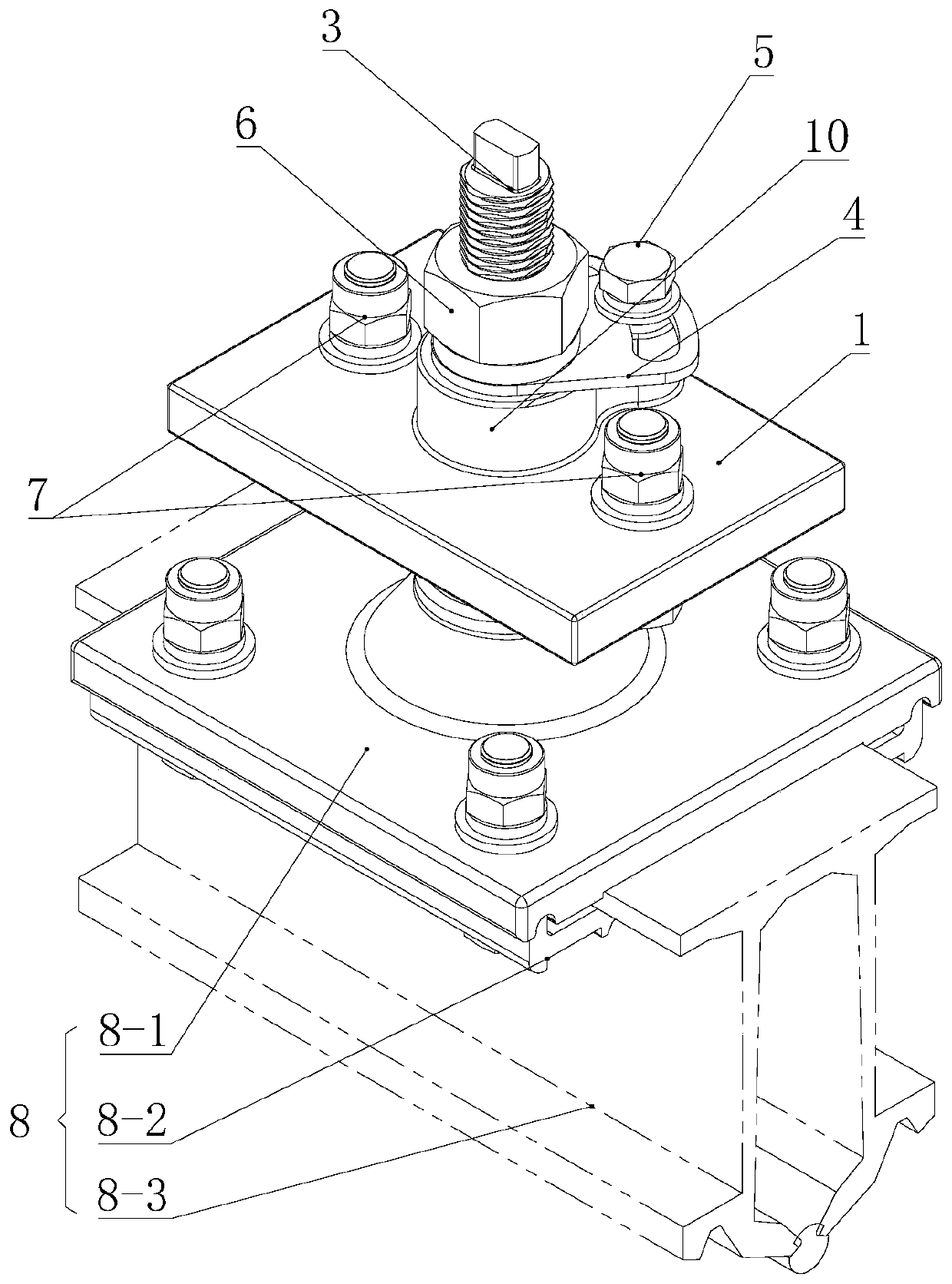
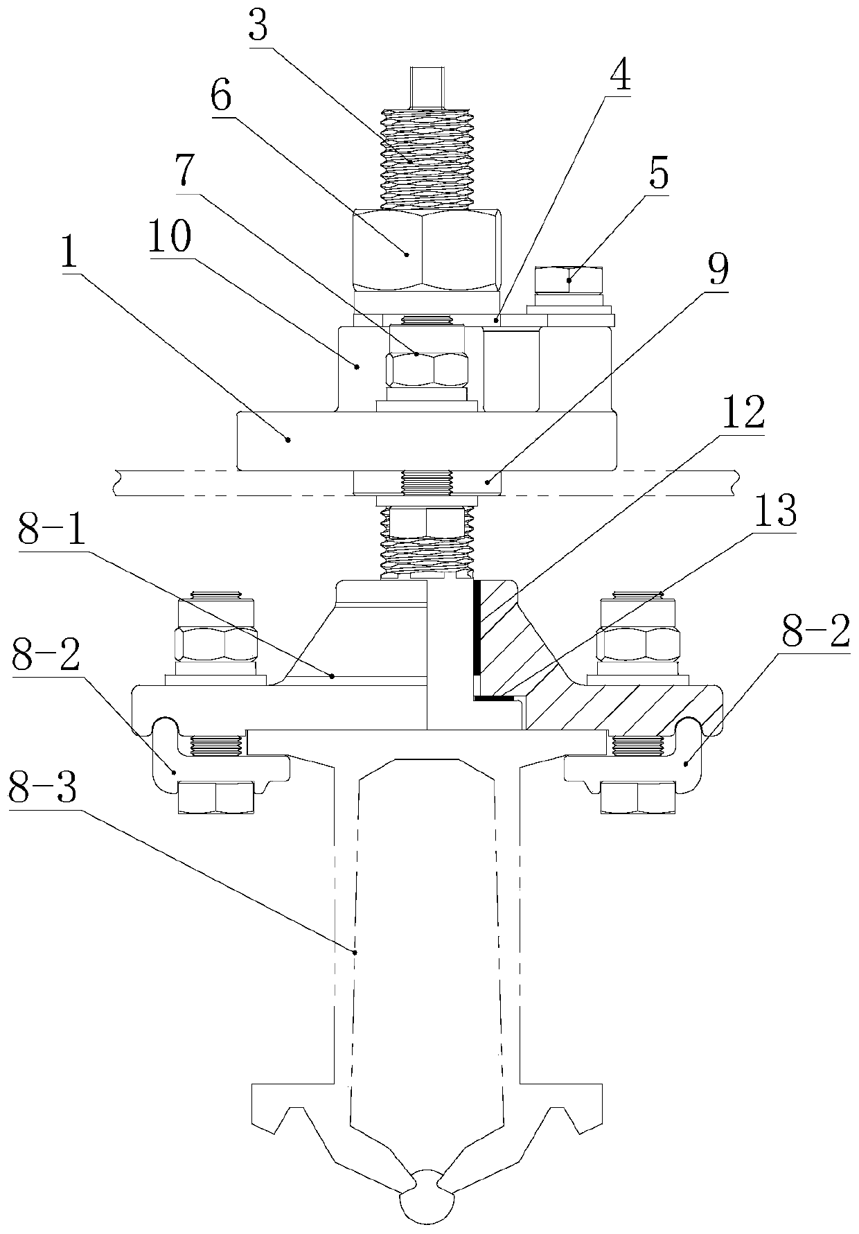
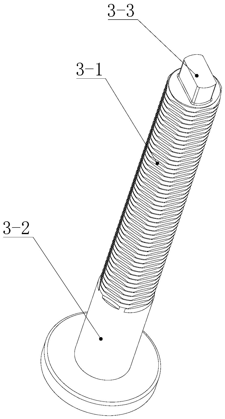
[0024] Such as figure 1 and figure 2 The shown suspension clamp includes a suspension seat 1, and a threaded through hole 2 is provided on the suspension seat 1, and a connecting shaft 3 is threaded in the threaded through hole 2, such as image 3 The connecting shaft 3 shown includes a regular hexagonal thread section 3-1 and a suspension section 3-2, the regular hexagonal thread section 3-1...


PUM


Abstract

The invention discloses a low clearance rotary adjustable supporting suspension wire clamp. The low clearance rotary adjustable supporting suspension wire clamp comprises a suspension seat (1); a threaded through hole (2) is formed in the suspension seat (1); a connecting shaft (3) is connected to the interior of the threaded through hole (2) through threads; the connecting shaft (3) comprises anorthohexagonal thread section (3-1) and a suspension section (3-2); the orthohexagonal thread section (3-1) is connected with the threaded through hole (2) through threads; an anti-rotation gasket (4)for preventing the connecting shaft (3) from rotating sleeves the orthohexagonal thread section (3-1); a fixing bolt (5) for fixing the rotation of the anti-rotation gasket (4) is arranged on the suspension seat (1); a fastening nut (6) used for pressing the anti-rotation gasket (4) on the suspension seat (1) is also arranged on the connecting shaft (3); a limiting bolt (7) for fixing the suspension seat (1) is also arranged on the suspension seat (1); and a busbar fixture (8) is movably suspended on the suspension section (3-2).

Description

technical field [0001] The invention relates to the field of rigid suspension systems for electrified railways and urban rail transit, in particular to a low-clearance rotary adjustable support suspension clamp. Background technique [0002] In the rigid suspension system, the clamp is installed on the cantilever or beam to support the suspension busbar. There are mainly two types of clamp product structures, which are used in the rigid suspension system of electrified railway and urban rail transit respectively. Among them, in the rigid suspension system of electrified railway, the wire clip is installed on the rotatable cantilever, and the busbar is fixed on the wire clip, and the displacement caused by the thermal expansion and cold contraction of the busbar can be adapted by the rotation of the cantilever. In the rigid suspension system of urban rail transit, the insulator is installed on the support beam, the wire clamp is fixed under the insulator, the bus bar is suspe...

Claims


Application Information

Patent Timeline
Patent Type & Authority Applications(China)
IPC IPC(8): B60M1/24
CPCY02E10/50
Inventor 邓相龙林建冯勇李忠齐龚建刚王小琴冉伟锋
Owner CHINA RAILWAY HIGH SPEED ELECTRIFICATION EQUIP CORP LTD
Learn More