Lifting type rain sewage tail-end ecological treatment device

A technology for ecological treatment and rainwater sewage, applied in the direction of biological water/sewage treatment, water/sludge/sewage treatment, chemical instruments and methods, etc., can solve the problems of small rotating centrifugal force, large fence size, heavy workload of filter material replacement, etc. problem, to achieve the effect of fast replacement and stable frame

Pending Publication Date: 2019-06-07
ZHEJIANG AIKELE ENVIRONMENTAL PROTECTION
View PDF0 Cites 2 Cited by
  • Summary
  • Abstract
  • Description
  • Claims
  • Application Information

AI Technical Summary

Problems solved by technology

Among them, the basic working principle of the cyclone separator as a separation and classification equipment is based on centrifugal sedimentation. When the separated two mixed liquids enter the interior of the cyclone separator tangentially from the upper periphery of the cyclone separator at a certain pressure, strong Due to the density difference between the light phase and the heavy phase, due to the centrifugal force, the heavier particles are deposited at the bottom of the cyclone, while most of the lighter materials are discharged from the overflow port, so as to achieve the purpose of separation. The disadvantage is that when the flow rate is small, the rotating centrifugal force is small and the separation effect is poor
The existing filtering device adopts a fence-type simple filtering device in front of the rain / sewage pipe mouth, that is, two steel pipes are installed on three sides around the rain / sewage pipe mouth and penetrated into the river bed of the river. The ceramsite filter material is filled between the steel pipe fences. With this structure, the size of the fence is large, the amount of on-site construction work is large, the construction period is long, the workload of filter material replacement is large, the overall structure is simple, and the aesthetics is poor.

Method used


Image

  • Lifting type rain sewage tail-end ecological treatment device
  • Lifting type rain sewage tail-end ecological treatment device
  • Lifting type rain sewage tail-end ecological treatment device

Examples


Embodiment Construction

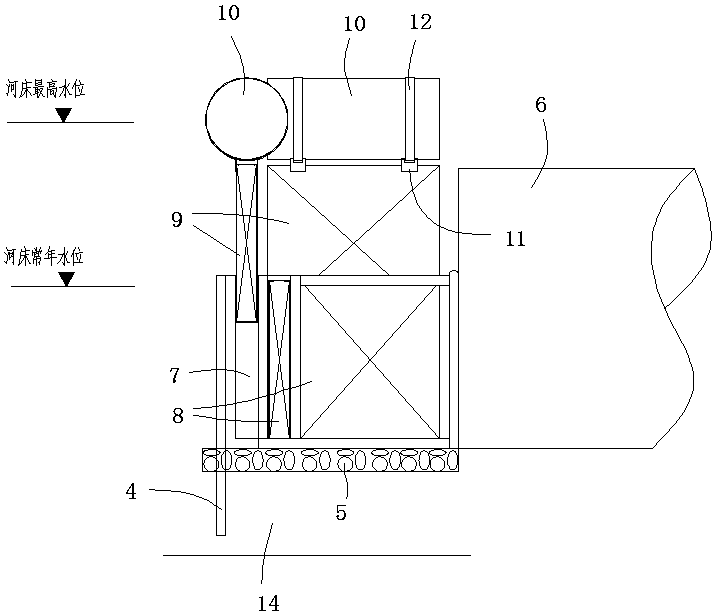
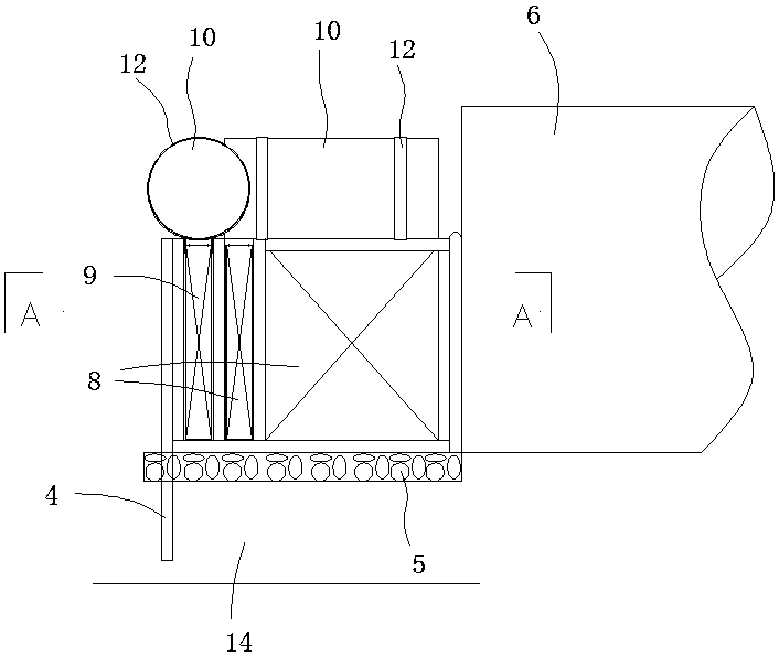
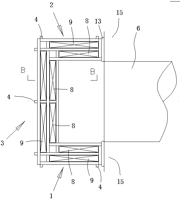
[0020] In order to make the technical solution of the present invention clearer, the following is combined with the appendix Figures 1 to 4 , the present invention will be described in detail. It should be understood that the specific embodiments described in this specification are only for explaining the present invention, but not for limiting the protection scope of the present invention.

[0021] The present invention is a lift-type rainwater and sewage terminal ecological treatment device, including a frame surrounding the outlet of a rainwater / sewage pipe 6 (a pipe that collects surface rainwater or sewage) arranged in a river, and the frame includes a left frame edge 1, a right side frame The frame edge 2, and the front-end frame edge 3 connected with the front ends of the left and right frame edges 1 and 2, between the frame and the river bottom 14, a gravel layer 5 is arranged, and the left, right, front The frame edges 1, 2, and 3 are all provided with inner and out...


PUM

PropertyMeasurementUnit
transparencyaaaaaaaaaa

Abstract

The invention discloses a lifting type rain sewage tail-end ecological treatment device. The device comprises a frame surrounding a rain / sewage pipe outlet of a river channel, the frame comprises a left side frame edge, a right side frame edge and a front end frame edge connected with the front end parts of the left and right side frame edges, and a gravel layer is arranged between the frame and ariver bottom; and the left side, right side, and front end frame edges are separately provided with inner and outer layer frame clamping grooves, each inner side adsorption module is inserted into one corresponding inner layer frame clamping groove, each outer side adsorption module is inserted into one corresponding outer layer frame clamping groove, and the top end of each outer side adsorptionmodule is connected with one corresponding buoy. The lifting type rain sewage tail-end ecological treatment device provided by the invention is very suitable for installation with water, and can realize quick replacement of the adsorption modules, and automatically adapt to change of a water level.

Description

technical field [0001] The present invention relates to a device for ecological treatment of rainwater / sewage discharged into a river. The ecological treatment of rainwater / sewage refers to not taking any purification treatment that is harmful to the river. For example, chemical treatment is non-ecological treatment. Background technique [0002] Improving the water quality of river systems is an important measure for urban ecological environment restoration, water environment safety and governance. The pollution incidents of the river system and the impact on water quality are caused by the internal pollution and the input of external pollution in the river. For the input of external pollution, it is mainly caused by more rain / sewage pipes on both sides of the river. The hazards of the rainwater pipes mainly come from two aspects: one is that the rainwater washes the ground with various pollutants (particulate matter, leaves, oil pollution, etc.); It is directly discharge...

Claims


Application Information

Patent Timeline
Patent Type & Authority Applications(China)
IPC IPC(8): C02F3/34
Inventor 邱屹俞觊觎王振魏星张建兵陈伟民章世邦周浩然
Owner ZHEJIANG AIKELE ENVIRONMENTAL PROTECTION
Why Eureka
Try Eureka