Sewage-removing gas-discharging device

An exhaust device and sewage pipe technology, which is applied in the fields of water/sewage multi-stage treatment, water/sludge/sewage treatment, chemical instruments and methods, etc. At the same time, it can achieve the effect of easy operation, improved performance and excellent sewage discharge effect.

Pending Publication Date: 2019-06-07
合肥瑞纳智能能源管理有限公司
View PDF0 Cites 2 Cited by
  • Summary
  • Abstract
  • Description
  • Claims
  • Application Information

AI Technical Summary

Problems solved by technology

[0002] At present, traditional pipeline decontamination devices are commonly divided into vertical straight-through decontamination devices, horizontal straight-through decontamination devices, horizontal corner-through decontamination devices, Y-type decontamination devices, and swirling flow decontamination devices. There is a problem of poor sewage discharge effect due to the aging of the structural design, and at the same time, it cannot meet the requirements of simultaneous use of pollution removal and exhaust. How to solve the existing technical problems and provide a new pollution removal and exhaust equipment has become an urgent need for personnel in the relevant technical fields. solved problem

Method used


Image

  • Sewage-removing gas-discharging device
  • Sewage-removing gas-discharging device
  • Sewage-removing gas-discharging device

Examples


Embodiment 1

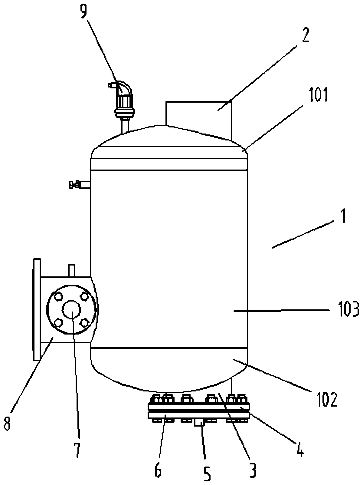
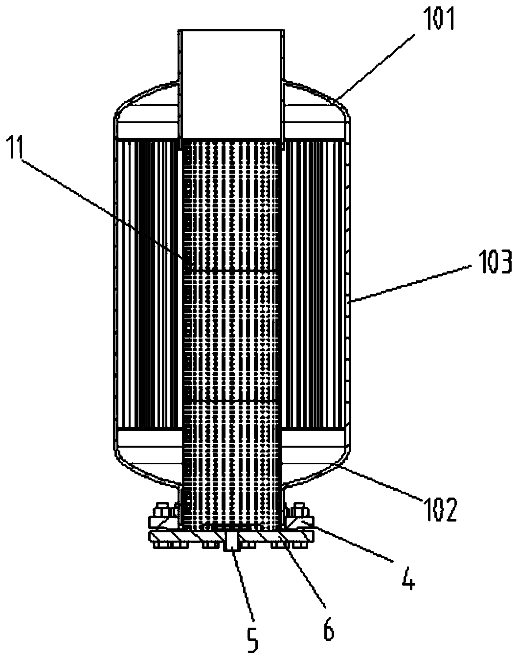
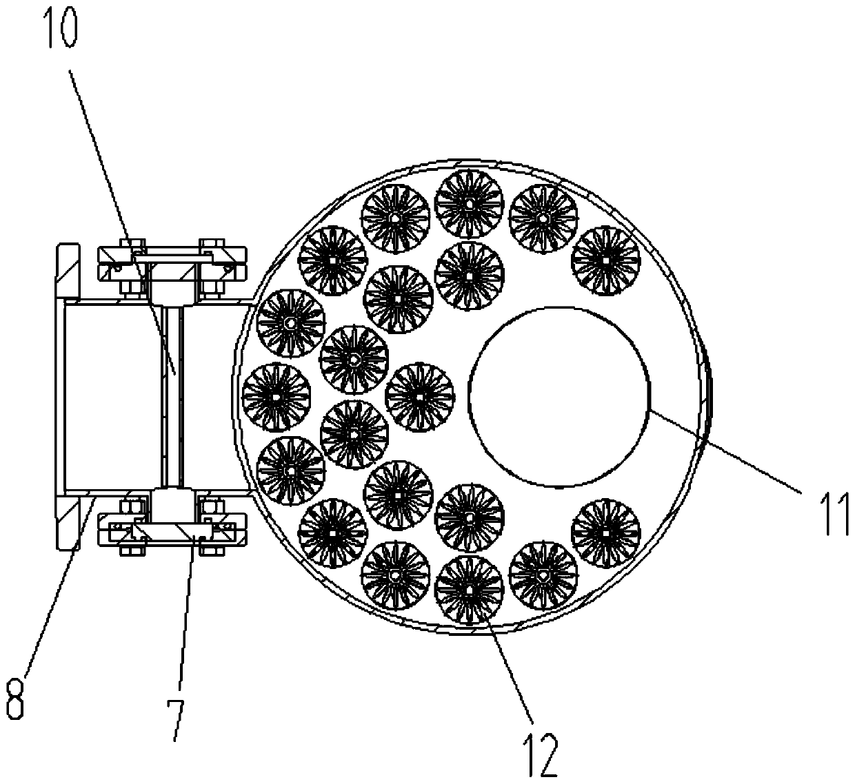
[0025] like Figure 1-4 As shown, the decontamination exhaust device includes a water inlet pipe 2 arranged on the upper part of the main body 1, and the main body 1 includes an upper cover 101, a lower cover 102 and a cylinder body 103, and the upper cover 101. The lower cover 102 is respectively sealed and connected to the upper and lower ends of the cylinder body 103. The top of the upper cover 101 is equipped with an automatic exhaust valve 9 for removing the gas in the inner cavity of the main body 1. The water inlet pipe 2 is installed On the top of the upper cover 101, and on one side of the automatic exhaust valve 9, the side wall of the main body 1 is horizontally provided with a water outlet pipe 8, and a pipe for observing the inner cavity of the main body 1 is installed on the pipe wall of the water outlet pipe 8. Sight glass 7, the bottom of the main body 1 is provided with a sewage pipe 3, the sewage pipe 3 is arranged along the horizontal central axis of the mai...

Embodiment 2

[0033] like Figure 5-7 As shown, the decontamination exhaust device includes a water inlet pipe 2 arranged on the upper part of the main body 1, and the main body 1 includes an upper cover 101, a lower cover 102 and a cylinder body 103, and the upper cover 101. The lower cover 102 is respectively sealed and connected to the upper and lower ends of the cylinder body 103. The top of the upper cover 101 is equipped with an automatic exhaust valve 9 for removing the gas in the inner cavity of the main body 1. The water inlet pipe 2 is installed On one side of the cylinder body 103, the pipeline design of this kind of water inlet pipe 2 can be applied to the tubular installation requirements of various pipelines; A speculum 7 for observing the inner cavity of the main body 1 is installed on the top. The bottom of the main body 1 is provided with a sewage pipe 3. The sewage pipe 3 is arranged along the horizontal central axis of the main body 1 and the water outlet pipe 8, and is a...


PUM


Abstract

The invention discloses a sewage-removing gas-discharging device. The device comprises a water inlet pipe arranged at the upper part of a main body, the side wall of the main body is horizontally provided with a water outlet pipe, and a sight glass used for observing an inner cavity of the main body is installed on the wall of the water outlet pipe; and the bottom of the main body is provided witha sewage discharging pipe, a filter screen coaxially arranged with the sewage discharging pipe is installed in the inner cavity of the main body, and the inner cavity of the main body is provided with bubble trapping nets uniformly distributed by using the filter screen as an axis and used for collecting filtered water bubbles. The device provided by the invention has a better sewage dischargingeffect in the process of ensuring high-efficiency sewage removal by means of a pipeline layout manner of one inlet and two outlets, at the same time, layout design of the bubble trapping nets in the device is combined, so that the device has the effect of effectively collecting the bubbles on a filtered water part; a neodymium iron boron magnet is rationally used to adsorb impurities of sewage inthe device, the structure is simpler, the device is easy to operate and does not require excessive maintenance, so that the use performance of the device is improved.

Description

technical field [0001] The invention relates to the technical field of pollution discharge, in particular to a pollution removal and exhaust device. Background technique [0002] At present, traditional pipeline decontamination devices are commonly divided into vertical straight-through decontamination devices, horizontal straight-through decontamination devices, horizontal corner-through decontamination devices, Y-type decontamination devices, and swirling flow decontamination devices. There is a problem of poor sewage discharge effect due to the aging of the structural design, and at the same time, it cannot meet the requirements of simultaneous use of pollution removal and exhaust. How to solve the existing technical problems and provide a new pollution removal and exhaust equipment has become an urgent need for personnel in the relevant technical fields. solved problem. Contents of the invention [0003] The object of the present invention is to provide a decontaminat...

Claims


Application Information

Patent Timeline
Patent Type & Authority Applications(China)
IPC IPC(8): C02F9/12
Inventor 李孝俊董君永张旭陶昌勤张世钰孙傲赵娅玲
Owner 合肥瑞纳智能能源管理有限公司
Why Eureka
Try Eureka