
High-pressure water lubrication compressor

A water-lubricated and compressor technology, applied in the field of compressors, can solve the problems of compressor axial force imbalance, bearing damage, rotor cannot reach high speed, etc., and achieve a stable balance effect

Inactive Publication Date: 2019-06-07
广东葆德科技有限公司
View PDF7 Cites 0 Cited by
  • Summary
  • Abstract
  • Description
  • Claims
  • Application Information

AI Technical Summary

Problems solved by technology

The disadvantage is that both the suction and exhaust ends of the female and male rotors use water-lubricated bearings to position the rotors radially and axially, and use pure water to lubricate and cool the bearings. Due to the limitations of water-lubricated bearings, the rotors cannot achieve optimal performance. high speed
In addition, oil-free water-lubricated twin-screw compressors are prone to wear in practice because the bearing part bears a large axial force. Not only the bearing wear will affect the working effect, but also the wear debris will cause wear of other parts along with the water lubricated water. , so it is often necessary to install a balance on the rotor to counteract the axial force, which not only takes up space, but also if the balance plate is installed inaccurately or the pressure fluctuates due to external force interference, the axial force of the compressor will be unbalanced, which will seriously cause bearing damage. damage

Method used


Image

  • High-pressure water lubrication compressor
  • High-pressure water lubrication compressor
  • High-pressure water lubrication compressor

Examples


Embodiment Construction

[0012] In order to make the purpose, technical solution and advantages of the present application clearer, the present invention will be further described in detail below in conjunction with the accompanying drawings and embodiments. In the ensuing description some specific details are referred to for a thorough understanding of the present invention. While the present invention can be practiced without these specific details, the description and representations herein can be used by those skilled in the art to more effectively convey the substance of their work to others skilled in the art.

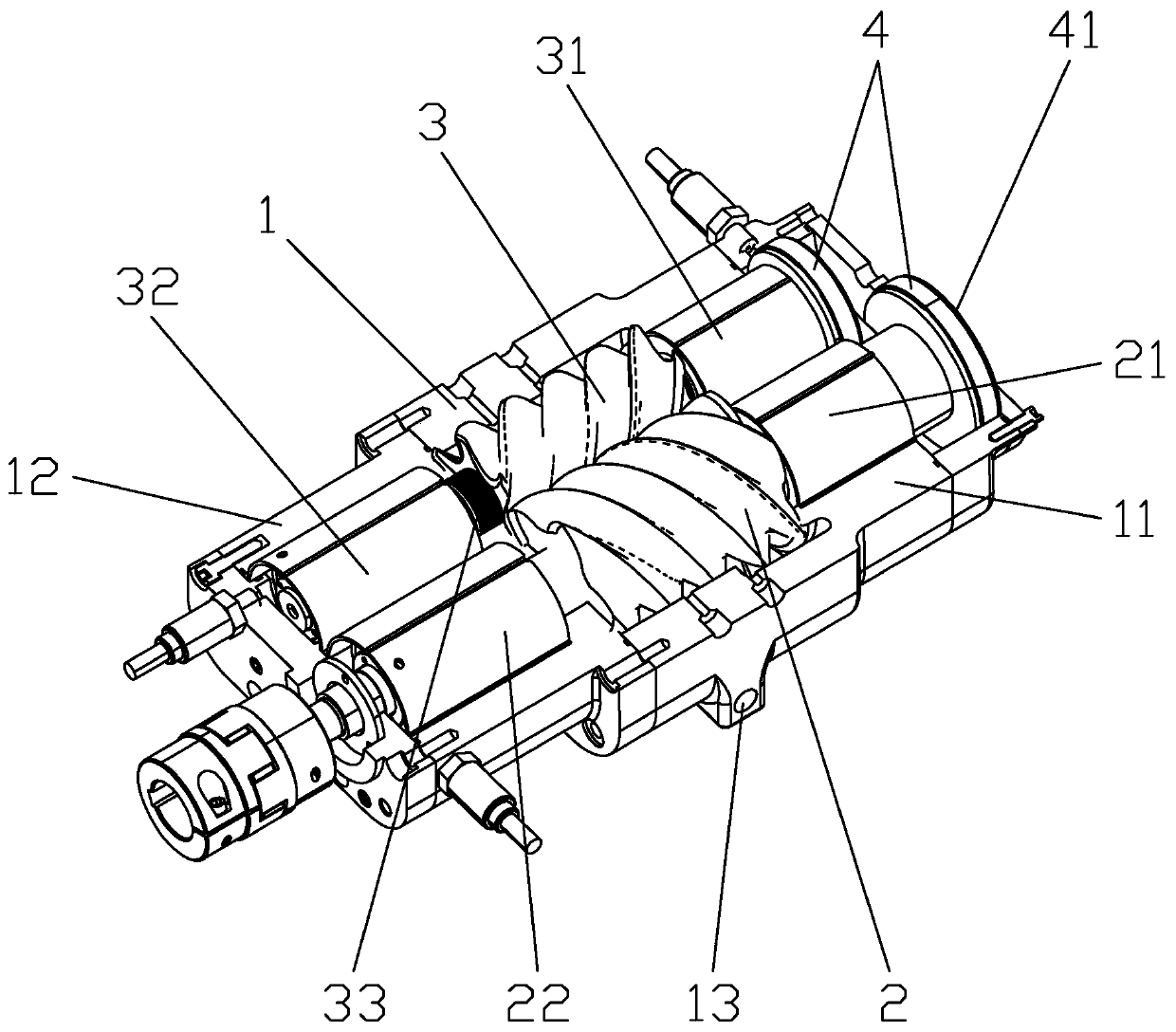
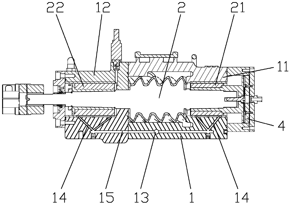
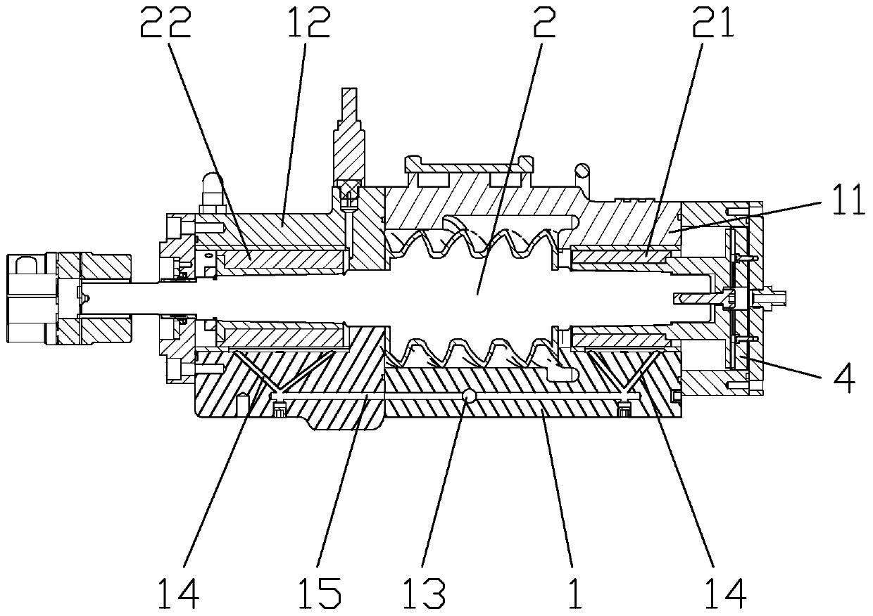
[0013] refer to figure 1 , figure 2 , a high-pressure water-lubricated compressor, including a casing 1, the casing 1 includes a suction side bearing seat 11, and a discharge side bearing seat 12, and the casing 1 has a built-in male rotor 2 and a female rotor 3, wherein the male The rotor 2 is fitted with a water-lubricated radial sliding bearing 21 on the suction side of the male ro...


PUM


Abstract

The invention discloses a high-pressure water lubrication compressor. The high-pressure water lubrication compressor comprises a shell, wherein the shell comprises an air suction side bearing block and an exhaust side bearing block, a male rotor and a female rotor are arranged in the shell, the male rotor is sleeved with a male rotor air suction side water lubrication radial sliding bearing and amale rotor exhaust side water lubrication radial sliding bearing, and the position of the air suction side bearing block corresponds to the male rotor air suction side water lubrication radial slidingbearing and a female rotor air suction side water lubrication radial sliding bearing, the exhaust side bearing block corresponding the male rotor exhaust side water lubrication radial sliding bearingand a female rotor exhaust side water lubrication radial sliding bearing is provided with a V-shaped water spraying opening; high-pressure water is injected into a high-pressure water inlet, high-pressure water is sprayed from the V-shaped water spraying opening to balance the axial force of the sliding bearing to replace the original balance plate structure, so that the balance effect is more stable, meanwhile, high-pressure water sprayed out by the V-shaped water spraying opening does not conflict with water lubrication, and auxiliary water lubrication can be carried out along the two sidesof the water lubrication radial sliding bearing.

Description

technical field [0001] The invention relates to the technical field of compressors, in particular to a high-pressure water lubricated compressor. Background technique [0002] Pure water is sprayed into the compression cavity of the oil-free water-lubricated twin-screw compressor as a lubricant for the male and female rotors and water-lubricated bearings. At the same time, the pure water is also used as a compressed gas coolant to absorb the compression heat generated during the gas compression process. Noise generated during gas compression. Because the pure water sprayed into this type of oil-free twin-screw compressor can be used as a lubricant, therefore, there is no need to set a synchronous gear between the male and female rotors. At this time, the main structure of the compressor is the simplest. The disadvantage is that both the suction and exhaust ends of the female and male rotors use water-lubricated bearings to position the rotors radially and axially, and use p...

Claims


Application Information

Patent Timeline
IPC IPC(8): F04C18/16F04C29/02
Inventor 郭振发
Owner 广东葆德科技有限公司
Learn More