

Liftable rack and refrigeration equipment
A technology for refrigeration equipment and racks, which is applied to the field of elevating racks and refrigeration equipment including the elevating racks, can solve the problems of uneven load bearing, difficulty in real-time absolute synchronization, and inclination of racks left and right, etc. Contact area, improve reliability, improve the effect of connection strength
- Summary
- Abstract
- Description
- Claims
- Application Information
AI Technical Summary
Problems solved by technology
Method used
Image

Examples
Embodiment 1
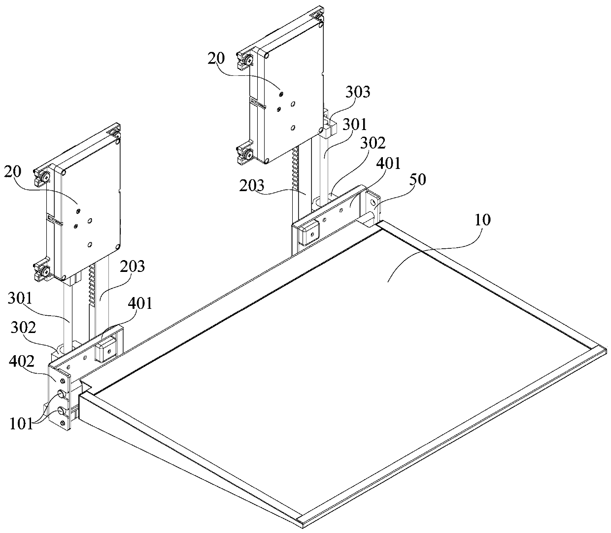
[0076] The rack body 10 includes: a support member, the drive mechanism 20 and the guide mechanism are fixedly connected with the support member, and the connecting parts of the drive mechanism 20, the guide mechanism and the support member are arranged along the width direction of the refrigeration equipment, and the support member includes A support plate 401 extending in the width direction of the device, such as figure 1 and figure 2 shown.
[0077] The shelf body 10 includes a support fixedly connected with the drive mechanism 20 and the guide mechanism for supporting the shelf body 10. The support plate 401, the drive mechanism 20 and the guide mechanism are connected to the support plate 401, and the connection parts with the support plate 401 are arranged at intervals along the width direction of the refrigeration equipment, which increases the distance between the drive mechanism 20, the guide mechanism and the shelf body 10. The contact area of the connection part...
Embodiment 2
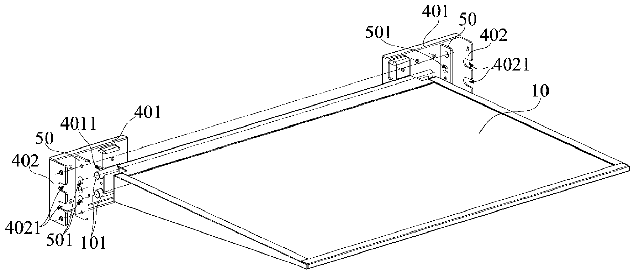
[0081] The difference from Embodiment 1 is that: the shelf body 10 also includes: a locking plate 50, which is arranged between the support and the frame, so that the frame and the support are indirectly connected, as figure 1 and figure 2 shown, as figure 1 and figure 2 shown.
[0082] The shelf body 10 also includes a locking plate 50 arranged between the support and the frame. The locking plate 50 can lock the frame and the support, so that the frame is indirectly connected with the support, further improving the connection between the frame and the support. Reliability of connections between supports.
[0083] Preferably, the locking plate 50 is provided with a relief hole 501, and the rear end of the frame body is provided with a support rod 101 matched with the relief hole 501, and the support rod 101 is fitted with the relief hole 501; The support plate 401 is connected to the side plate 402 extending to the front end of the frame body, and the side plate 402 is f...
Embodiment 3
[0103] The difference from Embodiment 1 and Embodiment 2 is that: on the basis of Embodiment 1 and Embodiment 2, further, the lifting shelf further includes: a detection mechanism, which cooperates with the transmission member, and is used to detect the position of the transmission member ; and a controller electrically connected to the detection mechanism and the driving part, and used to control the action of the driving part according to the detection result of the detection mechanism.
[0104] The lifting shelf also includes a detection mechanism and a controller. The detection mechanism can cooperate with the transmission part to detect the specific position of the transmission part. The controller is electrically connected with the detection mechanism and the drive part. When the transmission part moves to the highest position of the guide mechanism At the lowest point or the lowest point, the detection mechanism feeds back the position signal of the transmission part to ...
PUM
 Abstract
Description
Claims
Application Information