Magnetic angle sensor self-calibration method and device, magnetic angle sensor and system

A magnetic angle sensor and magnetic angle technology, which is applied in the direction of instruments, etc., can solve the problems of increasing test cost, consuming a long time for calibration, and reducing production efficiency, so as to achieve the effect of reducing test cost, reducing calibration time, and improving production efficiency

Active Publication Date: 2019-06-07
中电海康无锡科技有限公司
View PDF6 Cites 14 Cited by
  • Summary
  • Abstract
  • Description
  • Claims
  • Application Information

AI Technical Summary

Problems solved by technology

The current calibration method is mainly to find the maximum value by MCU self-comparison, or calculate the maximum and minimum values ​​after storing all the data in the next week through the host computer, and then return it to the MCU for subsequent calculations. The disadvantage of these two methods is that every angle point within 360° must be performed. Test, and with the increase of customers' accuracy requirements, the test points will become more and more dense, calibration will consume a lot of time, reduce production efficiency and increase test cost

Method used


Image

  • Magnetic angle sensor self-calibration method and device, magnetic angle sensor and system
  • Magnetic angle sensor self-calibration method and device, magnetic angle sensor and system
  • Magnetic angle sensor self-calibration method and device, magnetic angle sensor and system

Examples


Embodiment Construction

[0049] Specific embodiments of the present invention will be described in detail below in conjunction with the accompanying drawings. It should be understood that the specific embodiments described here are only used to illustrate and explain the present invention, and are not intended to limit the present invention.

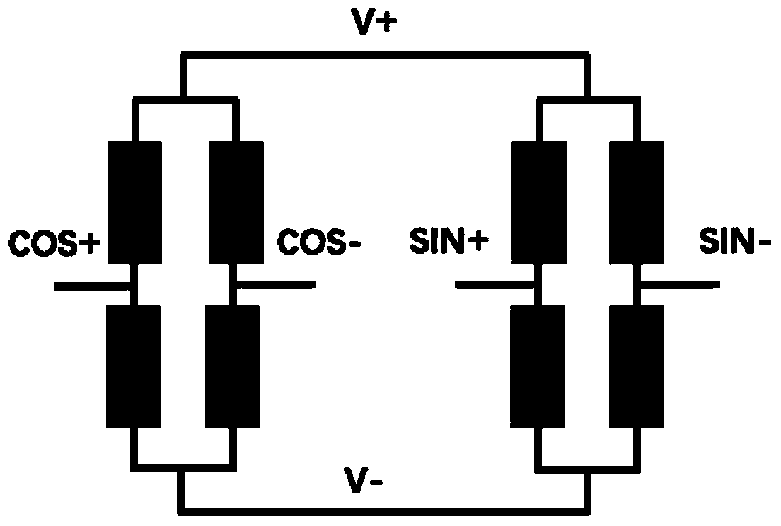
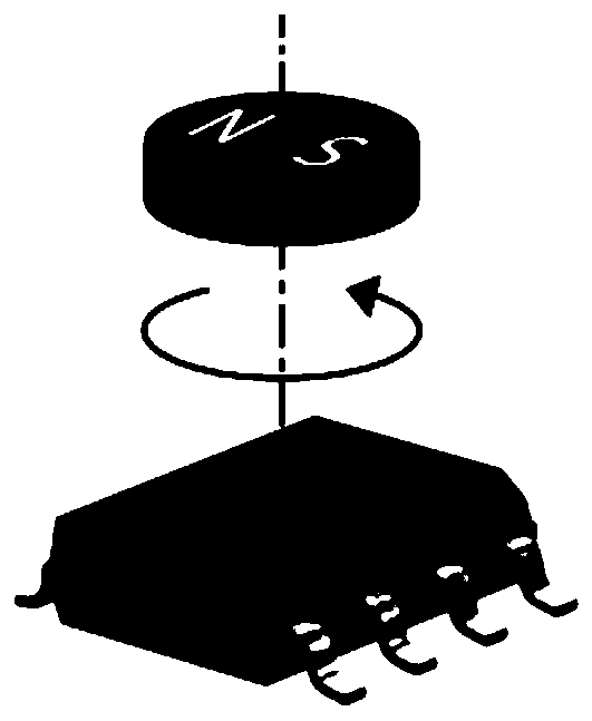
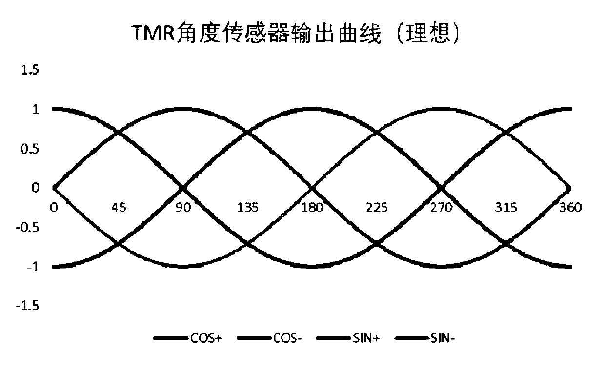
[0050]It should be noted that the magnetic angle sensor adopts a Wheatstone full-bridge structure in which the sensing directions are perpendicular to each other, and outputs two sets of differential analog signals SIN+, SIN-, COS+, COS-, and the difference is obtained to obtain X (COS) and Y (SIN). Such as figure 1 Shown is a schematic diagram of the internal structure of the magnetic angle sensor. figure 2 It is a schematic diagram of the angle sensor working under the magnetic field. image 3 It is the ideal output curve of the magnetic angle sensor. Figure 4 and Figure 5 Respectively, the image obtained after doing the difference and the corresponding...


PUM


Abstract

The invention relates to the technical field of magnetic angle sensors, and particularly discloses a magnetic angle sensor self-calibration method. The magnetic angle sensor self-calibration method comprises the following steps: obtaining a first group of magnetic angle data; obtaining a second group of magnetic angle data; processing the first group of magnetic angle data and the second group ofmagnetic angle data to obtain an angle value to be calibrated; and calibrating the magnetic angle sensor; wherein obtaining the first group of magnetic angle data and obtaining the second group of magnetic angle data both include the following steps: obtaining the current two channels of magnetic angle signal values of the magnetic angle sensor; determining whether to output a slow rotation driving signal of the motor or not according to the relationship between the current two channels of magnetic angle signal values and a first threshold range; and determining whether to output the two channels of magnetic angle signal values or not according to the relationship between the current two channels of magnetic angle signal values and a second threshold range. The invention also discloses a magnetic angle sensor self-calibration device, a magnetic angle sensor and a magnetic angle sensor system. The magnetic angle sensor self-calibration method provided by the invention greatly reduces the calibration time and improves the production efficiency.

Description

technical field [0001] The present invention relates to the technical field of magnetic angle sensors, in particular to a self-calibration method for a magnetic angle sensor, a self-calibration device for a magnetic angle sensor, a magnetic angle sensor comprising the self-calibration device for the magnetic angle sensor, and a magnetic angle sensor comprising the magnetic angle sensor magnetic angle sensor system. Background technique [0002] In the actual production process of the magnetic angle sensor, due to various reasons such as sensors, magnets, and assembly, the maxX, minX, maxY, and minY of each complete machine are different, so they need to be calibrated one by one. The current calibration method is mainly to find the maximum value by MCU self-comparison, or calculate the maximum and minimum values ​​after storing all the data in the next week through the host computer, and then return it to the MCU for subsequent calculations. The disadvantage of these two meth...

Claims


Application Information

Patent Timeline
Patent Type & Authority Applications(China)
IPC IPC(8): G01D18/00
Inventor 张立新陈佳俊金璞
Owner 中电海康无锡科技有限公司
Why Eureka
Try Eureka