Driving method of display panel

A technology of a display panel and a driving method, which is applied to static indicators, instruments, etc., can solve the problems of brightness difference and the effect of affecting the display, and achieve the effect of eliminating stripes and improving display quality.

Inactive Publication Date: 2019-06-07
WUHAN CHINA STAR OPTOELECTRONICS TECH CO LTD
View PDF4 Cites 1 Cited by
  • Summary
  • Abstract
  • Description
  • Claims
  • Application Information

AI Technical Summary

Problems solved by technology

This kind of driving method can reduce the area occupied by the fan-out routing of the data lines to achieve narrow borders. However, in the prior art, when scanning each row period in each frame period, the charging sequence of multiple sub-pixels 110 Both: charge the pixels 100 in the first and second columns first, and then charge the pixels 100 in the third and fourth columns. When the pixels are insufficiently charged and the common voltage fluctuates, the display effect of the pixels 100 charged first is better than that of the pixels 100 charged later. The display effect of the charged pixel 100 will eventually lead to such as image 3 As shown, there is an obvious difference in brightness between the pixels 100 in the first and second columns and the pixels 100 in the third and fourth columns, and then stripes appear on the screen displayed on the display panel, which affects the display effect

Method used


Image

  • Driving method of display panel
  • Driving method of display panel
  • Driving method of display panel

Examples


Embodiment Construction

[0043] In order to further illustrate the technical means adopted by the present invention and its effects, the following describes in detail in conjunction with preferred embodiments of the present invention and accompanying drawings.

[0044] see Figure 4 , the present invention provides a method for driving a display panel, comprising the following steps:

[0045] Step S1, providing a display panel;

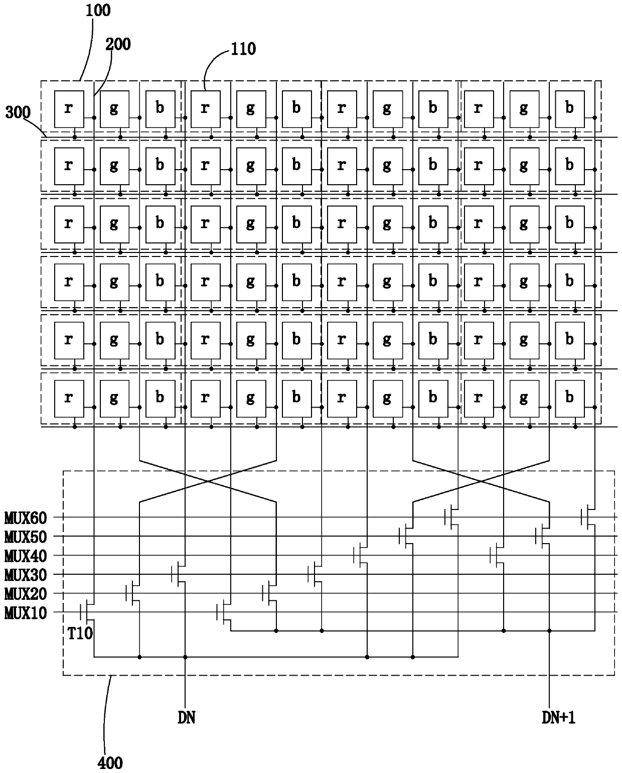
[0046] Such as Figure 5 As shown, the display panel includes a plurality of driving units; each driving unit includes a plurality of pixels 10 arranged in rows and 4 columns, 12 data lines 20 and a multiplexing module 40; each pixel 10 includes a row Three sub-pixels 11 in a row, the three sub-pixels 11 are the first sub-pixel 101, the second sub-pixel 102 and the third sub-pixel 103 in turn, the sub-pixels 11 of a plurality of pixels 10 are arranged in multiple rows and 12 columns, one piece of data The line 20 is correspondingly connected to a column of sub-pixels 11; t...


PUM


Abstract

The invention provides a driving method of a display panel. The driving method of the display panel comprises the following steps: enabling a first multiplexing signal, a second multiplexed signal, athird multiplexed signal, a fourth multiplexed signal, a fifth multiplexing signal and a sixth multiplexing signal to sequentially generate high-level pulses according to a first sequence in a first picture frame; enabling the first multiplexing signal, The second multiplexed signal, the third multiplexed signal, the fourth multiplexed signal, the fifth multiplexed signal and the sixth multiplexedsignal to sequentially generate high-level pulses according to a second order different from the first order in the second picture frame, so that the stripe feeling of a picture displayed by the display panel is eliminated through effect superposition of the first picture frame and the second picture frame, and the display quality is improved.

Description

technical field [0001] The present invention relates to the field of display technology, in particular to a driving method of a display panel. Background technique [0002] With the development of display technology, liquid crystal display (Liquid Crystal Display, LCD) and other flat display devices have gradually replaced cathode ray tubes (CathodeRay Tube, CRT) display screens are widely used in various consumer electronics products such as mobile phones, televisions, personal digital assistants, digital cameras, notebook computers, and desktop computers, and become the mainstream of display devices. [0003] Most of the liquid crystal display devices currently on the market are backlight liquid crystal display devices, which include a liquid crystal display panel and a backlight module. The working principle of the liquid crystal display panel is to inject liquid crystal molecules between the thin film transistor array substrate (Thin Film Transistor Array Substrate, TFT...

Claims


Application Information

Patent Timeline
Patent Type & Authority Applications(China)
IPC IPC(8): G09G3/36
CPCG09G3/36
Inventor 郑力华赵莽
Owner WUHAN CHINA STAR OPTOELECTRONICS TECH CO LTD
Why Eureka
Try Eureka