Busbar structure and cell module

A cell module and busbar technology, applied in structural parts, battery pack parts, circuits, etc., can solve the problems of high equipment requirements, complex process, inability to achieve mass production of large-sized modules, and reduce production. Process, simplify the product process, save the effect of production cost

Pending Publication Date: 2019-06-07
GUANGZHOU XIAOPENG MOTORS TECH CO LTD
View PDF0 Cites 4 Cited by
  • Summary
  • Abstract
  • Description
  • Claims
  • Application Information

AI Technical Summary

Problems solved by technology

[0002] At present, the cylindrical cell module is generally composed of multiple single cells connected in series. First, several cells are connected in parallel to form a group, and then multiple groups of cells are connected in series to form a module; each group of cells is connected in series. The negative direction is the same, and the positive and negative directions of the adjacent groups of cells are just opposite. Connect the positive pole of one group of cells and the negative pole of the other group of cells through a whole busbar to realize the series connection between each group of cells, so The bus bar needs to be arranged on both sides of the module. When the module is produced, it is necessary to fix the bus bar on one side first, and then turn over and fix the bus bar on the other side as a whole. When the bus bar is directly welded to the battery cell, it also needs to be turned back and forth. Welding, which requires high equipment and complicated processes, cannot achieve mass production of larger-sized modules

Method used


Image

  • Busbar structure and cell module
  • Busbar structure and cell module
  • Busbar structure and cell module

Examples


Embodiment Construction

[0031] This part will describe the specific embodiment of the present invention in detail, and the preferred embodiment of the present invention is shown in the accompanying drawings. Each technical feature and overall technical solution of the invention, but it should not be understood as a limitation on the protection scope of the present invention.

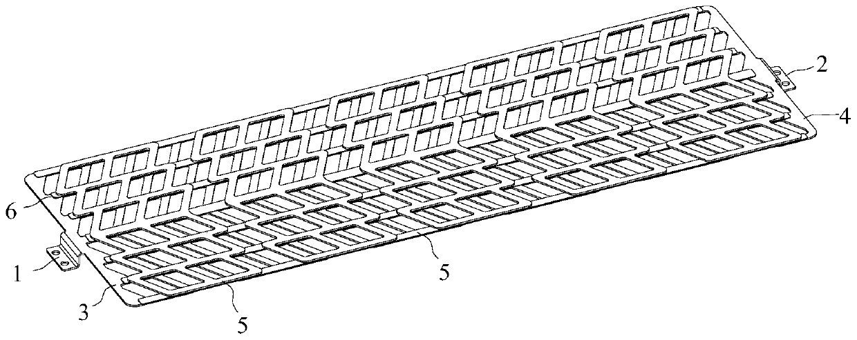
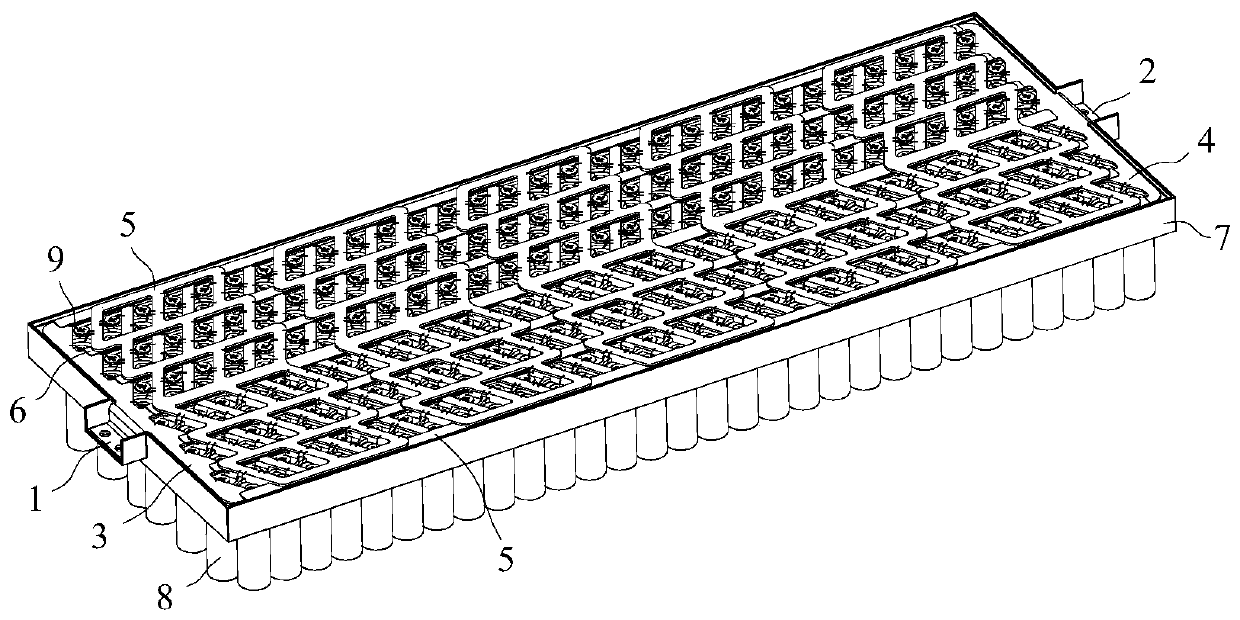
[0032] In the present invention, if the direction (up, down, left, right, front and back) is described, it is figure 1 , image 3 The structure shown is a reference description, but it is only for the convenience of describing the technical solution of the present invention, rather than indicating or implying that the technical features referred to must have a specific orientation, be constructed and operated in a specific orientation, so it cannot be understood as a reference to the technical solution of the present invention. Invention Limitations.

[0033] In the present invention, the meaning of "several" is one or more, ...


PUM


Abstract

The invention discloses a busbar structure and a cell module. The busbar structure comprises: a positive output pole; a negative output pole; a positive output pole busbar connected with the positiveoutput pole; a negative pole busbar connected with the negative output pole; and a plurality of intermediate busbars having a cell anode connection portion and a cell cathode connection portion, wherein the cell anode connection portion of the first intermediate busbar and the positive output pole busbar are insulated from each other and are distributed in a stack mode, and the cell cathode connection portion of the last intermediate busbar and the negative pole busbar are insulated from each other and are distributed in a stack mode. The cell module comprises a module holding member providedwith a cell matching structure; the cell array comprises a plurality of monomer cells which have cathodes facing the module holding member and are matched with the cell matching structure. The busbarstructure is arranged on the module holding member, the monomer cells of the cell array are connected through the busbar structure to form the cell module. The product process can be effectively simplified, the production process is reduced, and the production cost is saved.

Description

technical field [0001] The invention is used in the field of battery packs, and in particular relates to a bus bar structure and a battery core module. Background technique [0002] At present, the cylindrical cell module is generally composed of multiple single cells connected in series. First, several cells are connected in parallel to form a group, and then multiple groups of cells are connected in series to form a module; each group of cells is connected in series. The negative direction is the same, and the positive and negative directions of the adjacent groups of cells are just opposite. Connect the positive pole of one group of cells and the negative pole of the other group of cells through a whole busbar to realize the series connection between each group of cells, so The bus bar needs to be arranged on both sides of the module. When the module is produced, it is necessary to fix the bus bar on one side first, and then turn over and fix the bus bar on the other side...

Claims


Application Information

Patent Timeline
Patent Type & Authority Applications(China)
IPC IPC(8): H01M2/26H01M2/20
CPCY02E60/10
Inventor 李碧雄徐峰王杭挺刘安龙李林郑小凯李玉杰
Owner GUANGZHOU XIAOPENG MOTORS TECH CO LTD
Why Eureka
Try Eureka