Charging seat

A charging stand and a technology to be charged, which is applied in the direction of current collectors, electric vehicles, electrical components, etc., can solve problems such as inability to charge, coating peeling off, pogo pin corrosion, etc., to avoid long-term exposure, avoid corrosion, and prolong service life Effect

Pending Publication Date: 2019-06-07
GEER TECH CO LTD
View PDF5 Cites 3 Cited by
  • Summary
  • Abstract
  • Description
  • Claims
  • Application Information

AI Technical Summary

Problems solved by technology

[0004] From the above solution, it can be seen that the magnetic charging stand has the following technical defects: the top of the pogo pin is exposed for a long time, and it is easy to cause friction and collision with other substances, causing its coating to fall off, and the pogo pin is corroded, so that charging cannot be realized.
[0005] Therefore, how to design a charging stand that prevents the pogo pins from being corroded by the outside world and prevents the long-term exposure of the pogo pins from affecting the charging performance and can meet the charging function is a technical problem that needs to be solved at this stage.

Method used


Image

  • Charging seat
  • Charging seat
  • Charging seat

Examples


Embodiment 1

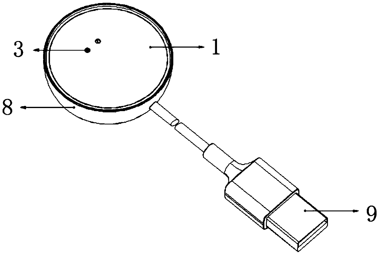
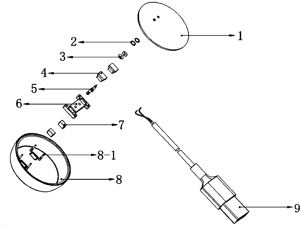
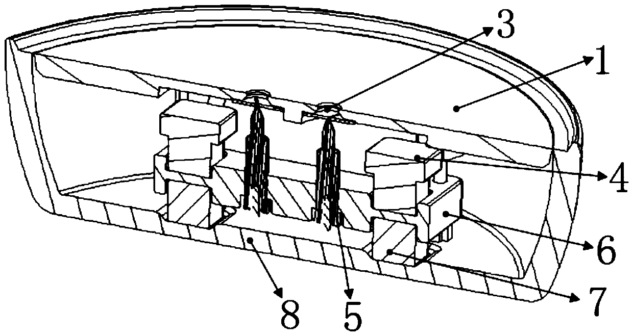
[0031] Such as figure 1 and figure 2 As shown, a charging stand is used in conjunction with a device to be charged with a built-in magnetic attraction. An accommodation cavity is formed, the electrical connector 5 is arranged inside the accommodation cavity, the USB cable passes through the lower case 8 of the charging stand and the electrical connector 5 is welded and assembled to the lower case 8 of the charging stand, and the accommodation cavity also includes a socket for driving the electrical connector 5 from The telescopic part protruding from the upper shell 1 of the charging stand, and the electrical connector 5 are initially fixed in the accommodating cavity. The magnetic parts attract each other and protrude out of the upper shell 1 of the charging stand to realize electrical contact with the charging terminal of the main body of the device to be charged. Wherein, the electrical connector 5 is a pogo pin or a copper pillar.

[0032] Specifically, the telescopic ...

Embodiment 2

[0038] Considering from the perspective of assembly process, the bracket 6 can use a regular-shaped structure, and the bracket 6 is set as a column structure. For this reason, on the basis of Embodiment 1, the following optimal structure of the bracket 6 is given:

[0039] Such as Figure 7 and Figure 8 As shown, the bracket 6 is arranged parallel to the upper shell 1 of the charging base, the middle part of the bracket 6 is fixedly provided with an electrical connector 5, the top surface of the bracket 6 is also provided with a groove structure for fixing the bracket magnet 4, and the bottom of the lower shell 8 of the charging base is in phase with the bracket magnet 4. The lower casing magnet 4 is fixedly arranged at the corresponding position.

[0040]In order to arrange the bracket magnet 4 on the bracket 6 more stably, a groove structure is fixedly arranged on the top surface of the bracket 6, so that the bracket magnet 4 can be stably positioned in the groove of the b...

Embodiment 3

[0046] On the basis of Embodiment 1 and Embodiment 2, in order to realize the fixation of the bracket 6 along the horizontal direction parallel to the upper case 1 of the charging stand, it is necessary to fix the guide part in the accommodating cavity and at the edge of the bracket 6, wherein the guide The structure of the department preferably adopts the following structure:

[0047] Such as Figure 5 and Figure 6 As shown, guide rail 11-1 is selected as guide part, and guide rail 11-1 is arranged on the four corners of bracket 18, and guide rail channel hole 6-1 is set at four corners of bracket 6, and guide rail 11-1 is arranged on guide rail channel hole 6-1 The gap between the inside and the guide rail 11-1 and the guide rail channel hole 6-1 is small enough to realize the sliding fit between the bracket 6 and the guide rail 11-1, and then realize the horizontal direction of the bracket 6 parallel to the upper shell 1 of the charging stand. fixed.

[0048] The specif...


PUM


Abstract

The invention discloses a charging seat, which comprises a charging seat upper shell, a charging seat lower shell and an electric connector. The charging seat upper shell and the charging seat lower shell are assembled to form an accommodating cavity, the electric connector is arranged inside the accommodating cavity, the accommodating cavity further comprises a telescopic part for driving the electric connector to extend out from the charging seat upper shell, the electric connector is fixed into the accommodating cavity in an initial state, when to-be-charged equipment is placed on the charging seat upper shell, the electric connector is mutually attracted with a magnetic part in a to-be-charged equipment body along with the telescopic part so as to extend out of the charging seat uppershell, and electric contact with the electric connector and a charging terminal of the to-be-charged equipment body is realized. When the charging seat is implemented, the electric connector is concealed in the accommodating cavity constituted by the charging seat upper shell and the charging seat lower shell, when being attracted by the outside, the electric connector extends out of the chargingseat upper shell to realize charging, and the technical effect that the electric connector is prevented from being exposed for a long term and corroded by the outside is achieved.

Description

technical field [0001] The invention relates to the technical field of smart wearable devices, in particular to a charging stand. Background technique [0002] With the rapid development of electronic science and technology, smart wearable devices are favored by consumers, especially smart bracelets and smart watches, which are worn on consumers' wrists, have received widespread attention and praise. [0003] In the prior art, wrist-worn devices such as smart watches and smart bracelets are small in size and fast in power consumption, and need to be charged with the help of an external accessory, namely a charging stand. At this stage, a magnetic charging stand is usually used to charge wrist-worn devices. The common structure of the charging stand is that the top of the pogo pin is exposed in the through hole of the upper shell of the charging stand. The pogo pins make electrical contact for charging. [0004] It can be seen from the above solution that the magnetic charg...

Claims


Application Information

Patent Timeline
Patent Type & Authority Applications(China)
IPC IPC(8): H02J7/00
Inventor 李松岩杜林
Owner GEER TECH CO LTD
Why Eureka
Try Eureka