Novel rotor applied to high-speed permanent magnet motor

A technology for permanent magnet motors and rotors, which is applied in the direction of magnetic circuit rotating parts, electric components, electrical components, etc., can solve the problems of low operating reliability, low power density, and low structural strength of permanent magnet motors, and achieve good heat dissipation , large electromagnetic torque, and the effect of improving operational reliability

Inactive Publication Date: 2019-06-07
SHANGHAI UNIV
View PDF5 Cites 1 Cited by
  • Summary
  • Abstract
  • Description
  • Claims
  • Application Information

AI Technical Summary

Problems solved by technology

[0005] The purpose of the present invention is to overcome the deficiencies of the above-mentioned prior art, and provide a new type of rotor applied to high-speed permanent magnet moto

Method used


Image

  • Novel rotor applied to high-speed permanent magnet motor
  • Novel rotor applied to high-speed permanent magnet motor
  • Novel rotor applied to high-speed permanent magnet motor

Examples


Embodiment 1

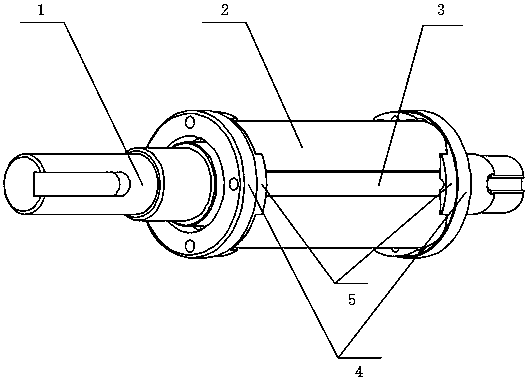
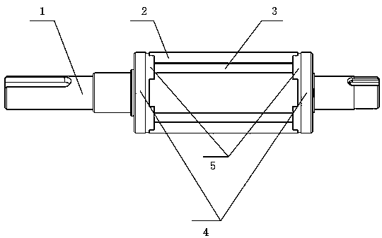
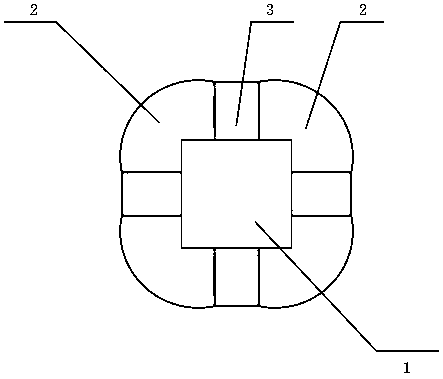
[0019] see Figure 1 to Figure 4 , a new type of rotor applied to high-speed permanent magnet motors, including a rotating shaft 1, a main permanent magnet 2, a transverse magnetization permanent magnet 3 and a magnetic isolation copper ring 4, characterized in that: the rotating shaft 1 is a polygonal rotating shaft, and the polygonal top Embedding the main permanent magnet 2 at an angle and fixing the main permanent magnet 2 circumferentially, on the one hand, increasing the adsorption force between the main permanent magnet 2 and the rotating shaft, can enhance the radial fixing of the permanent magnet to resist the centrifugal force at high speed; on the other hand On the one hand, the waveform of the air gap magnetic field is improved, and the loss is reduced; the magnetic isolation copper ring 4 is an approximate cup-shaped structure, and the magnetic isolation fixed wall 5 on it is tightly fastened to the two axial ends of the main permanent magnet 2, so as to realize th...

Embodiment 2

[0021] This embodiment is basically the same as Embodiment 1, and the special features are as follows:

[0022] The combination of the transverse magnetism gathering structure and the surface-mounted rotor is used to gather magnetism through a transverse magnetism gathering permanent magnet 3 between the two main permanent magnets 2, and utilize the magnetic monopole characteristic of the magnetism gathering structure, that is, the transverse magnetism gathering The magnetic field distribution on both sides of the structure is extremely uneven, and the magnetic field intensity on the side close to the air gap is significantly higher than that on the side close to the rotating shaft; therefore, the magnetic field lines enter the main magnetic pole from the transverse magnetic accumulation permanent magnet 3 through the contact surface of the adjacent permanent magnet This means that the magnetic field strength at the center of the contact surface between the main magnetic pole a...

Embodiment 3

[0027] Such as figure 1 As shown in the figure, the traditional circular shaft is changed to the polygonal shaft 1 in the figure, and the permanent magnet 2 with the opposite magnetization direction is embedded in the vertex of the polygonal shaft to fix the permanent magnet 2 to avoid damage caused by the huge centrifugal force at high speed. . By adding transverse magnetization permanent magnet 3 between permanent magnets 2 to form a transverse magnetic field structure for magnetization concentration, the thickness of the rotor core can be greatly weakened or even completely eliminated, thereby reducing the size of the rotor and finally realizing the size of the motor shrinking.


PUM


Abstract

The present invention discloses a novel rotor applied to a high-speed permanent magnet motor. Part of a circular rotating shafts are changed to a polygonal rotating shaft, the apex of the polygon is inlaid into a main permanent magnet to perform circumferential fixation of the permanent magnet so as to increase the adsorption power between the permanent magnet and the rotating shaft, enhance the radial fixing of the permanent magnet to resist the centrifugal force in a high rotation speed, improve the air-gap field waveform and reduce the loss. A non-magnetic copper ring is modified to an approximate cup-shaped structure to achieve axial and radial fixing of the permanent magnet while achieving non-magnetic and dynamic balance functions. A common rotor sheath fixing device is omitted to simplify the system structure. The omission of the sheath reduces the equivalent gas length to obtain a larger electromagnetic torque in the same motor dimension parameters so as to increase the power density of the motor. The problem of the fixing of the rotor permanent magnet is solved, the utilization efficiency of the permanent magnet is improved and the operation reliability of the motor is improved to facilitate lightweight of the high-speed permanent magnet motor and facilitate improvement of the operation speed of the motor and improvement of the performances of the motor.

Description

technical field [0001] The invention relates to the field of motors, in particular to a novel rotor applied to high-speed permanent magnet motors. Background technique [0002] With the vigorous development of the robot industry, its application in industrial production, household services and other fields is also becoming more and more extensive. The servo motor as the power source device of the robot is the key factor affecting the working performance of the robot. Therefore, high-speed permanent magnet motors are an important development direction of future motors. [0003] The purpose of optimizing the design of high-speed permanent magnet motors is to increase the power-to-weight ratio density of the motor and improve the dynamic and static performance of the motor. The optimal design of the rotor structure is an important part of it. The rotor of a high-speed permanent magnet motor often runs at tens of thousands or even hundreds of thousands of revolutions per minut...

Claims


Application Information

Patent Timeline
IPC IPC(8): H02K1/27H02K1/28H02K7/00
Inventor 罗建王寻杜萌王越陈淳
Owner SHANGHAI UNIV
Why Eureka
Try Eureka