Armature rolling dip machine and its armature carrier and armature fixture

A technology of armature and fixture, which is applied in the field of armature roll dipping machine and its armature carrier and armature fixture, which can solve the problems of poor consistency of dipping depth and achieve the effect of improving the consistency

Active Publication Date: 2021-03-23
湖南中伟智能制造有限公司
View PDF4 Cites 0 Cited by
  • Summary
  • Abstract
  • Description
  • Claims
  • Application Information

AI Technical Summary

Problems solved by technology

[0003] Based on this, it is necessary to provide an armature roll dipping machine and its armature carrier and armature fixture to solve the problem of poor consistency of dipping depth at both ends of the armature

Method used


Image

  • Armature rolling dip machine and its armature carrier and armature fixture
  • Armature rolling dip machine and its armature carrier and armature fixture
  • Armature rolling dip machine and its armature carrier and armature fixture

Examples


Embodiment Construction

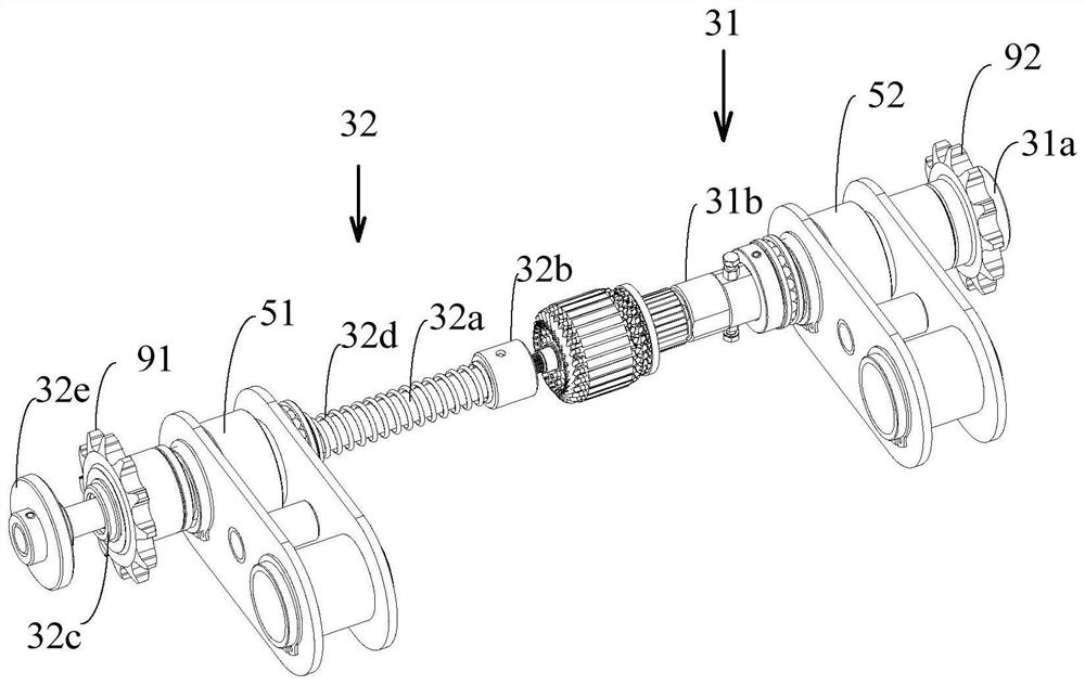
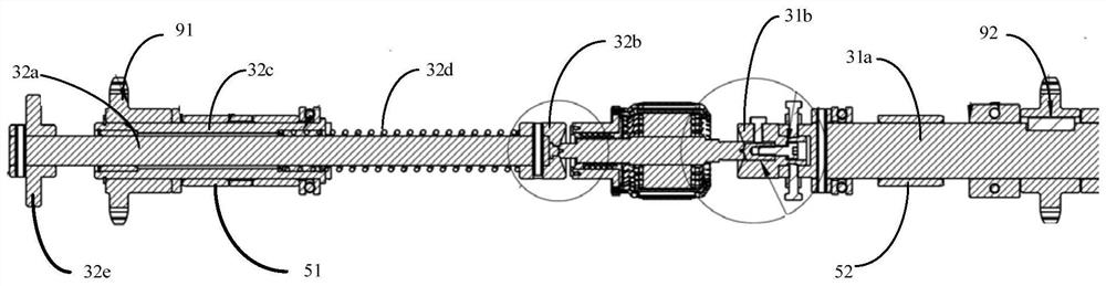
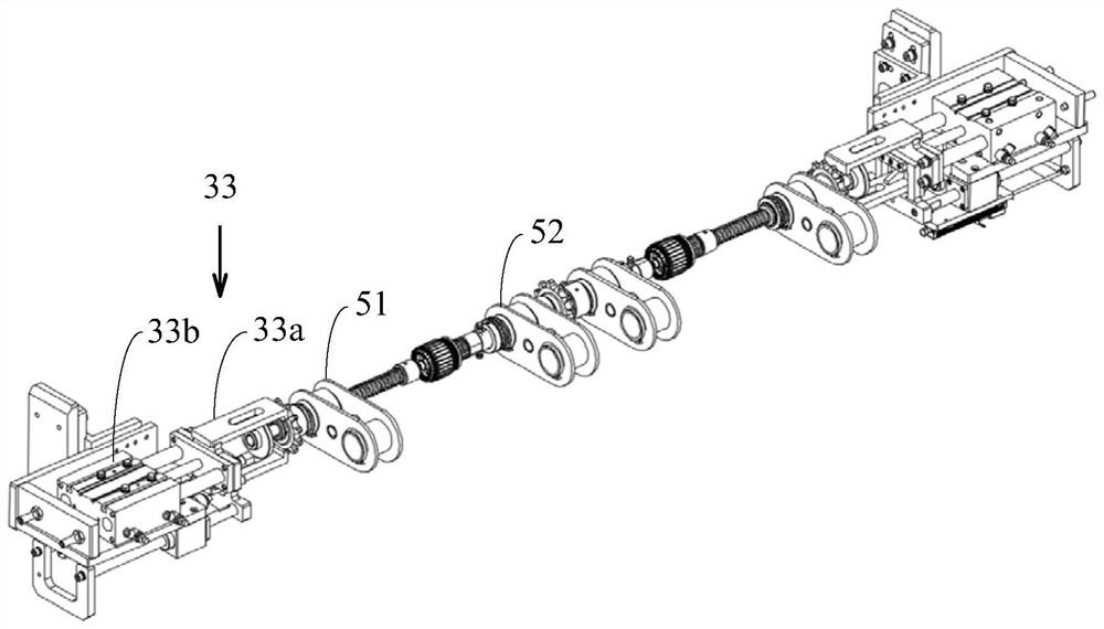
[0036] The present invention proposes an armature clamp, referring to Figure 1 to Figure 3 , the armature clamp includes a positioning mechanism 31, a pushing mechanism 32 and a material return mechanism 33; the positioning mechanism 31 includes a positioning rod 31a and a positioning seat 31b arranged at one end of the positioning rod 31a; the pushing mechanism 32 includes a coaxial The push rod 32a provided, the push seat 32b that is arranged on one end of the push rod 32a and is opposite to the positioning seat 31b, the push sleeve 32c that is sleeved on the push rod 32a, is sleeved on the push rod 32a and The push spring 32d located between the push sleeve 32c and the push seat 32b and the return member 32e arranged at the other end of the push rod 32a; the positioning seat 31b is coaxially arranged with the push seat 32b, and the opposite sides of the two Conical concave cavities are respectively arranged on the center, the armature is resisted by the positioning seat 31...


PUM


Abstract

The invention discloses an armature clamp which comprises a locating mechanism, a material pushing mechanism and a material return mechanism, wherein the locating mechanism comprises a locating rod and a locating seat arranged at one end of the locating rod; the material pushing mechanism comprises a material pushing rod coaxially arranged with the locating rod, a material pushing seat arranged atone end of the material pushing rod and opposite to the locating seat, a material pushing sleeve arranged on the material pushing rod in a sleeving manner, a material pushing spring arranged on the material pushing rod in a sleeving manner and located between the material pushing sleeve and the material pushing seat, and a material return piece arranged at the other end of the material pushing rod; tapered concave cavities with opposite centers are respectively arranged on opposite surfaces of the locating seat and the material pushing seat; the tapered concave cavities are respectively coaxial with the locating rod and the material pushing rod; an armature butts against the locating seat and the material pushing seat; the material pushing spring provides a butting force for butting against the armature; and the material return mechanism comprises a material return hook adapted to a material return piece and a material return driver driving the material return hook to pull the material pushing rod to retract. The armature clamp solves the problem of poor paint dipping depth consistency at the two ends of the armature due to easy off-axis clamping of the clamp in a rolling and dipping process.

Description

technical field [0001] The invention relates to the field of armature rolling dipping, in particular to an armature rolling dipping machine, an armature carrier and an armature clamp. Background technique [0002] After the armature is assembled and before the stator is installed in the motor, in order to further enhance the insulation and mechanical stability of the armature rotor, the armature rotor is usually put into a paint dipping furnace for dipping treatment. The process of dipping often involves clamping the armature into the fixture for processing in the dipping furnace. In the prior art, the armature fixture generally adopts single-end clamping, and the fixture is easy to clamp the armature off-axis during the rolling dipping process. The consistency of dipping paint depth at both ends of the armature is poor. Contents of the invention [0003] Based on this, it is necessary to provide an armature roll dipping machine, an armature carrier and an armature clamp ...

Claims


Application Information

Patent Timeline
Patent Type & Authority Patents(China)
IPC IPC(8): H02K15/12
Inventor 邓细平唐西成
Owner 湖南中伟智能制造有限公司
Why Eureka
Try Eureka