Linear motor

A linear motor and coil technology, applied in electrical components, electromechanical devices, etc., can solve the problems of smaller outer diameter, loud noise, and larger diameter, and achieve the effects of reducing production processes, simplifying manufacturing, and saving costs

Active Publication Date: 2019-06-07
DEYI PRECISION ELECTRONIC IND CO LTD PANYU
View PDF7 Cites 1 Cited by
  • Summary
  • Abstract
  • Description
  • Claims
  • Application Information

AI Technical Summary

Problems solved by technology

However, adding an additional shaft is equivalent to adding components. In order to match the shaft, it is necessary to further drill holes on the counterweight and the housing in addition to the magnet, which increases the cost and production process; meanwhile, because the shaft passes through the magnet, counterweight and The hole on the housing, during the vibration process, the shaft will rub against the magnet, the counterweight and the housing, which not only produces a lot of noise, but also after repeated vibrations, the wear of the counterweight will cause damage to the vibration path of the vibration unit. Metal powder will be produced on the surface of the vibration unit, which will affect the normal vibration of the vibration unit. The friction between the housing and the shaft will make the diameter of the hole on the housing used to fix the shaft larger, and the outer diameter of the shaft will become smaller, so that there is a gap between the shaft and the through hole. If looseness occurs, the shaft cannot play a guiding role during the vibration of the vibration unit and will further generate greater noise, which is not conducive to the normal use of the linear motor

Method used


Image

  • Linear motor
  • Linear motor
  • Linear motor

Examples


Embodiment Construction

[0033] In order to facilitate a better understanding of the purpose, structure, features, and effects of the present invention, the present invention will now be further described in conjunction with the accompanying drawings and specific embodiments.

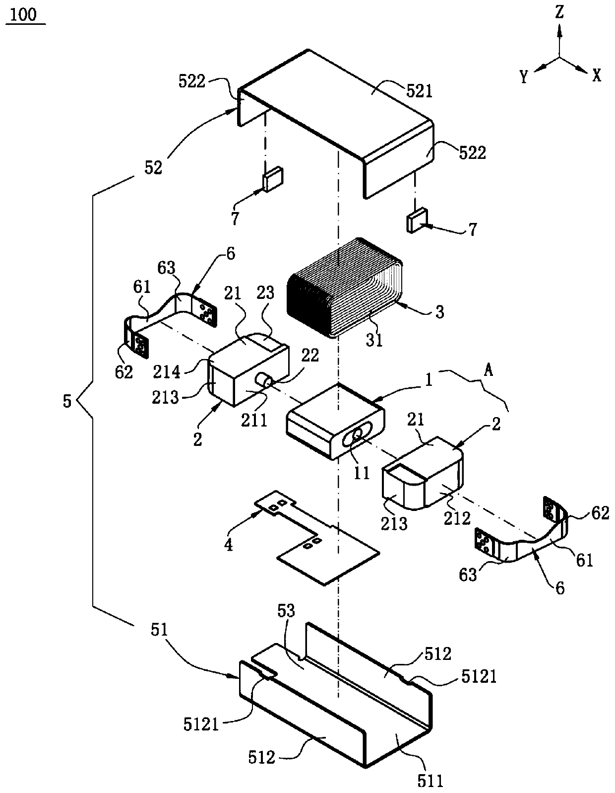
[0034] For ease of description, in this embodiment, the front-back direction (equivalent to the vibration direction) is defined as the X direction, the left-right direction is the Y direction perpendicular to the X direction, and the up-down direction is the Z direction perpendicular to the X direction and the Y direction.

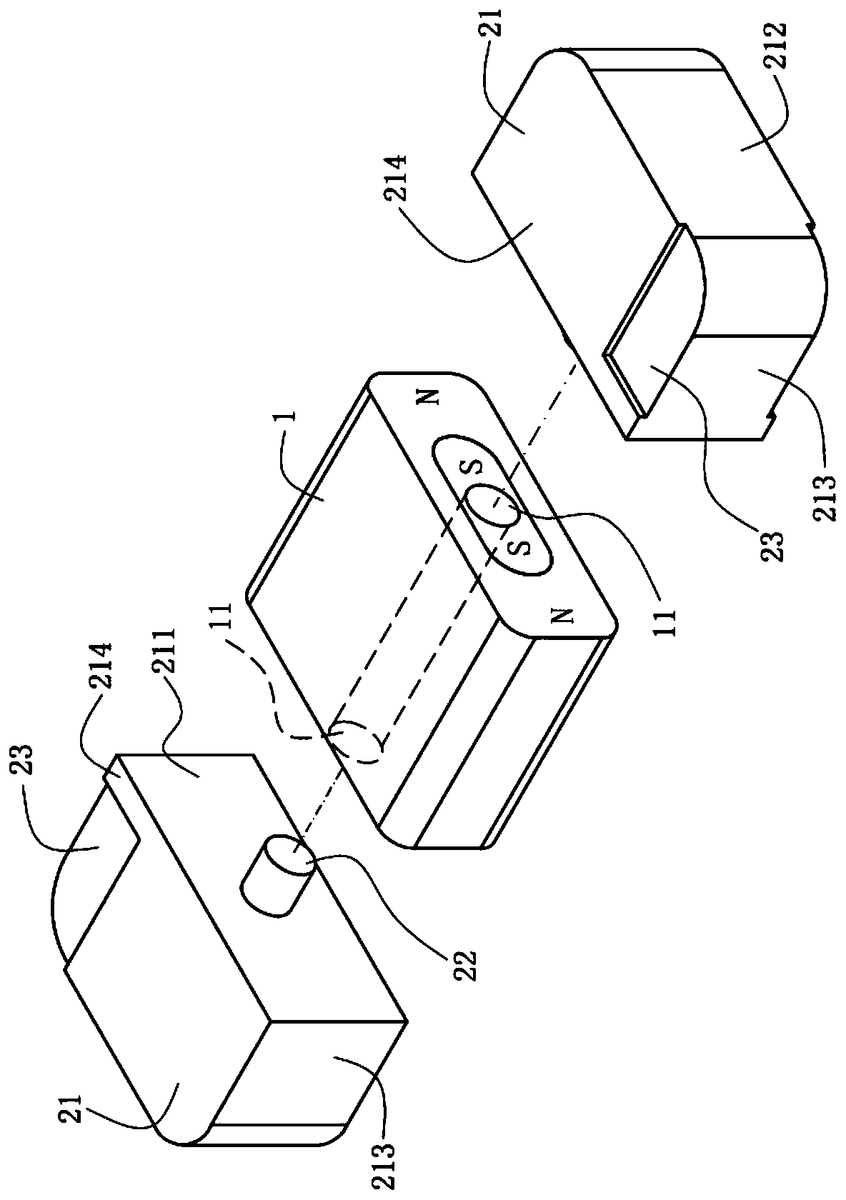
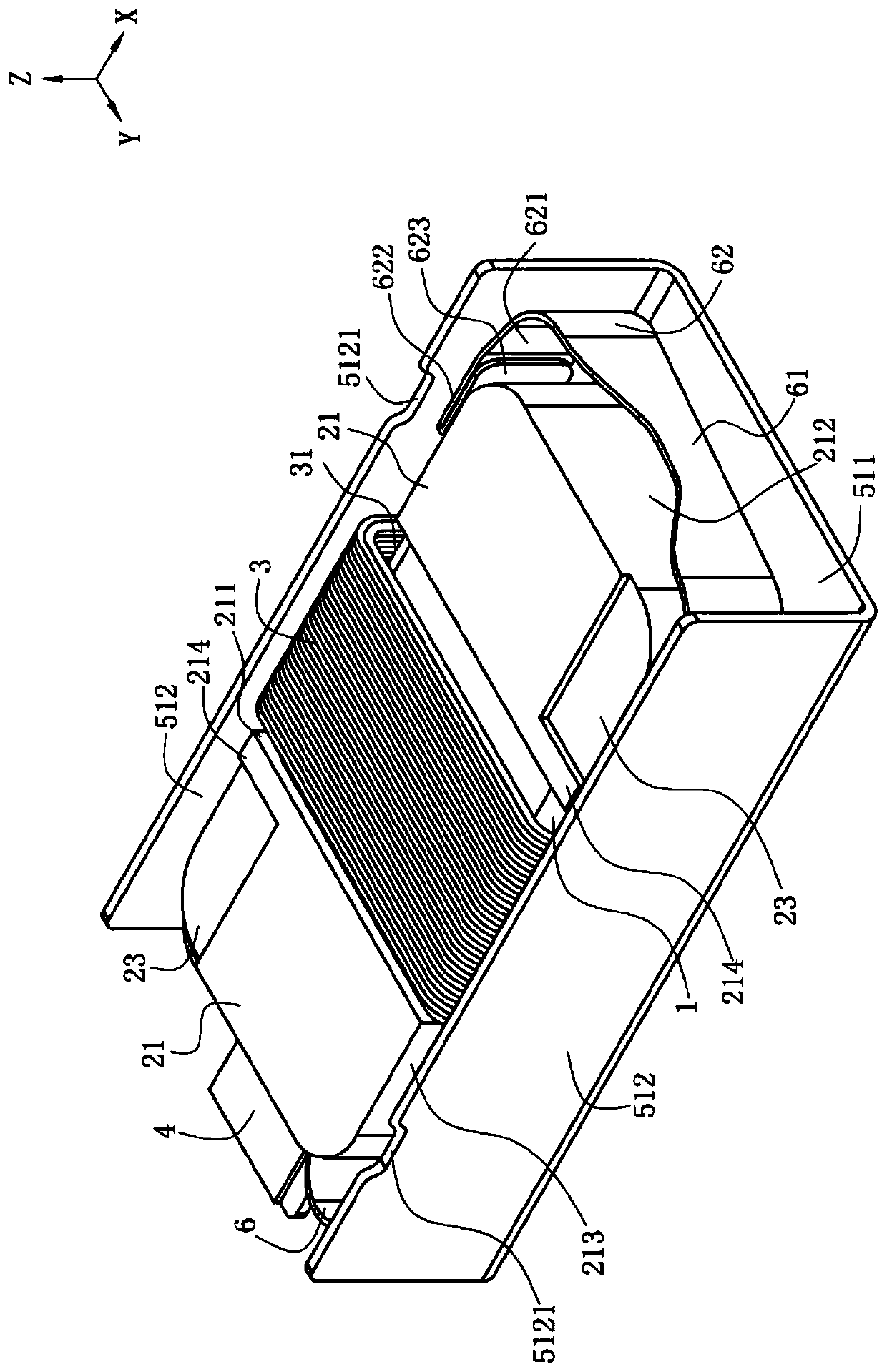
[0035] Please refer to Figure 1 to Figure 7 , is the first embodiment of a linear motor 100 of the present invention, the linear motor 100 includes a mover A (comprising a magnetic element 11 and two masses 2) vibrating along the vibration direction, a coil 3, a circuit board 4 , a housing 5 , two reset members 6 , and two buffer members 7 .

[0036] Please refer to figure 1 , figure 2 and Figure 5 ,...


PUM


Abstract

The invention discloses a linear motor, which is characterized by comprising a rotor, a shell, at least one reset piece and a coil, wherein the rotor comprises a magnetic element, at least one side ofthe magnetic element is provided with a positioning hole, at least one mass block is arranged at one side of the magnetic element, the mass block is provided with a positioning part which is formed integrally, and the positioning part enters the positioning hole; the shell accommodates the rotor; the at least one reset piece and the coil are accommodated in the shell; the coil is located outsidethe magnetic element, and through energizing the coil, the rotor abuts against the reset piece for back-forth repeated vibration in the shell, the positioning is accurate and the making is simple.

Description

【Technical field】 [0001] The invention relates to a linear motor, in particular to a linear motor used in electronic products. 【Background technique】 [0002] A conventional linear motor includes a vibrating unit, the vibrating unit has a magnet and two metal counterweights located on opposite sides of the magnet; There is a shrapnel between the casing and the coil. The vibration unit can vibrate repeatedly in the casing by energizing the coil and the force of the shrapnel. Usually, in order to guide the vibration unit to vibrate in a predetermined direction, an additional shaft passing through a magnet and a counterweight are set. The opposite sides of the block and the housing are fixed to the housing so that the vibration unit can only move linearly along the direction in which the shaft extends. However, adding an additional shaft is equivalent to adding components. In order to match the shaft, it is necessary to further drill holes on the counterweight and the housing ...

Claims


Application Information

Patent Timeline
IPC IPC(8): H02K33/02
Inventor 韩林万磊廖洁
Owner DEYI PRECISION ELECTRONIC IND CO LTD PANYU
Why Eureka
Try Eureka