
Converter power device

A technology of power devices and converters, which is applied in the direction of output power conversion devices, support structure installation, circuit layout on support structures, etc., and can solve the problems of damaged parts of capacitor components, easy-to-touch and damaged parts, etc.

Inactive Publication Date: 2019-06-07
GUODIAN LONGYUAN ELECTRICAL
View PDF1 Cites 0 Cited by
  • Summary
  • Abstract
  • Description
  • Claims
  • Application Information

AI Technical Summary

Problems solved by technology

[0004] When parts belonging to one of the functional components need to be replaced and repaired, it is easy to touch and damage parts belonging to another functional component, for example, when parts belonging to the power component need to be replaced, parts belonging to the capacitor component may be damaged

Method used


Image

  • Converter power device
  • Converter power device
  • Converter power device

Examples


Embodiment Construction

[0029] In order to enable those skilled in the art to better understand the technical solutions of the present invention, the present invention will be described in detail below in conjunction with the accompanying drawings and specific embodiments.

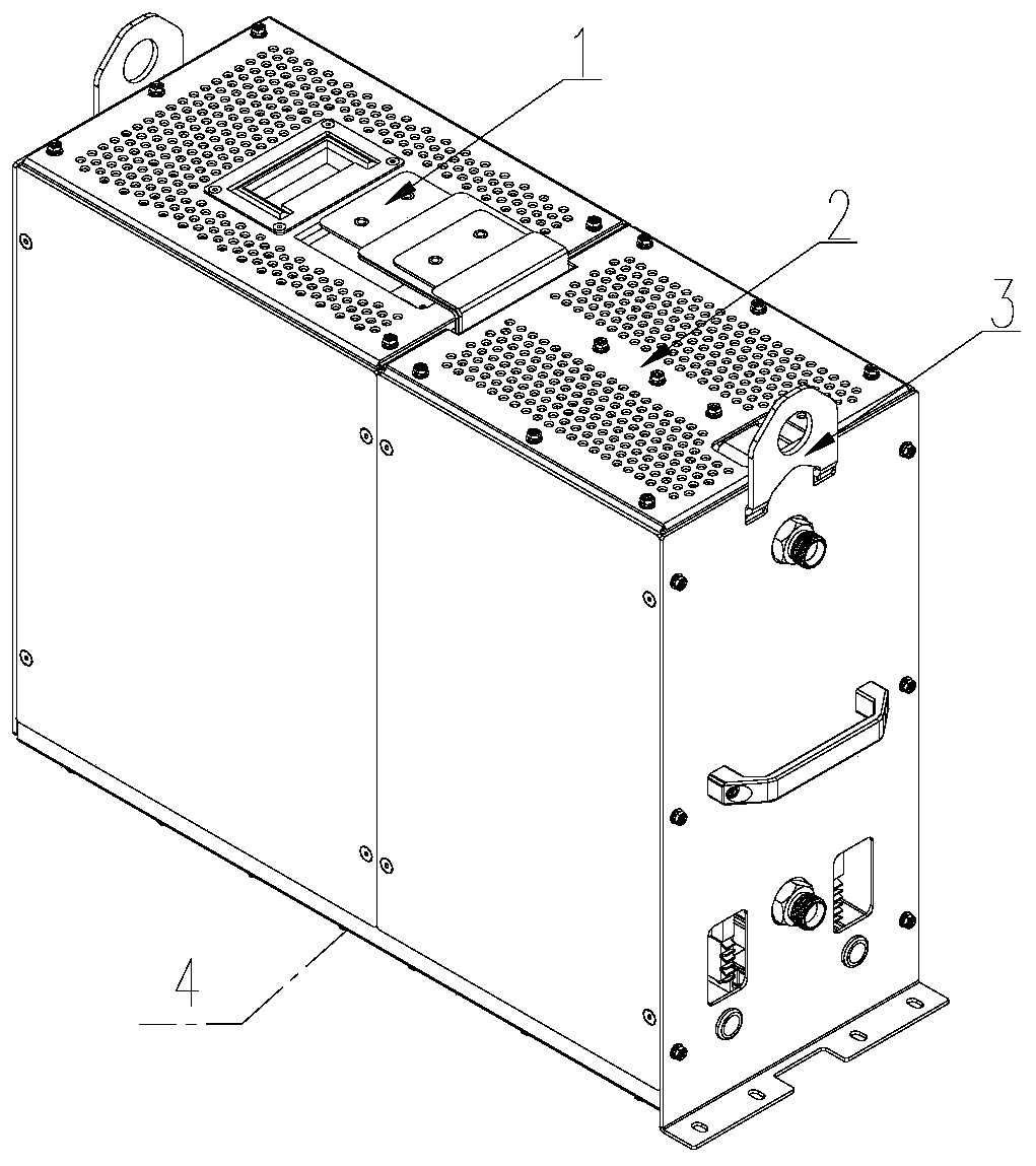
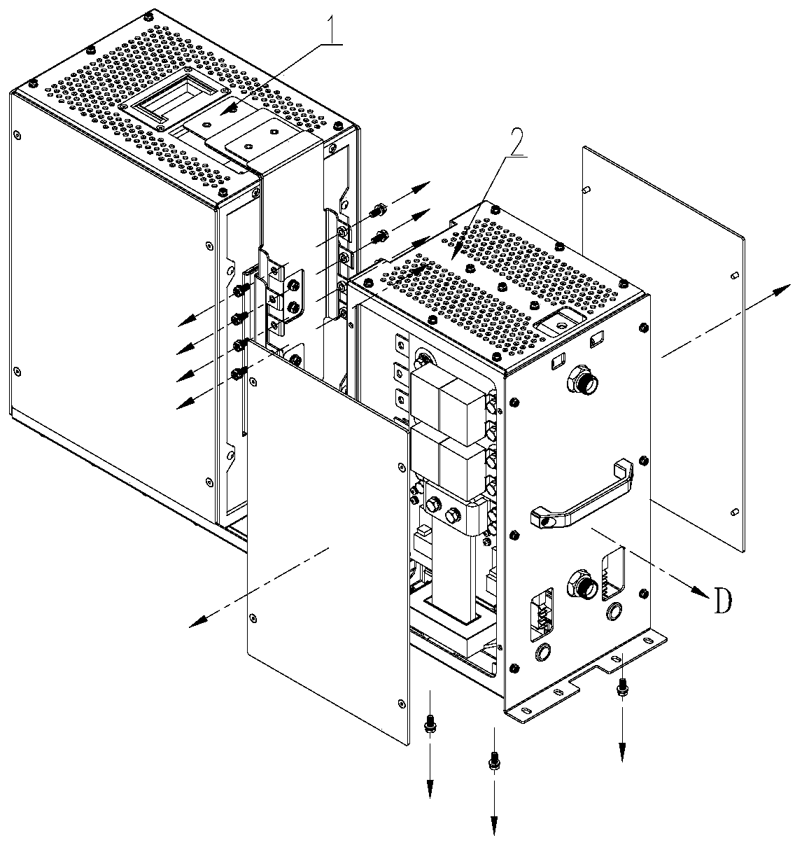
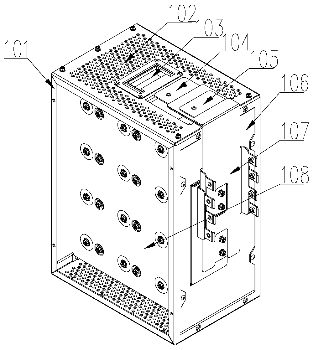
[0030] The embodiment of the present invention discloses a converter power device, which includes: a holding body, a power component 2 and a capacitor component 1 . In the present invention, two installation spaces spaced apart from each other are formed in the holding body, and the two installation spaces correspond to the components belonging to the power assembly 2 and the components belonging to the capacitor assembly 1 respectively.

[0031] The advantage that above-mentioned embodiment has is:

[0032] The present invention arranges two installation spaces isolated from each other, and respectively installs components belonging to different functional components in the two spaces, so that when the components belonging to th...


PUM


Abstract

The invention discloses a converter power device. The converter power device comprises a retaining body, a power component and a capacitor component, wherein the retaining body is internally providedwith two mounting spaces separated from each other, and the two mounting spaces respectively correspond to mounting of a part belonging to the power component and a part belonging to the capacitor component. According to the converter power device, the two separated mounting spaces are arranged, parts belonging to different functional components are respectively mounted in the two spaces, and whenthe parts of the functional components belong to the spaces are repaired and replaced, the parts of the other functional component in the spaces are not affected or damaged.

Description

technical field [0001] The invention relates to the technical field of wind power, in particular to a power device of a wind power converter. Background technique [0002] With the continuous improvement of the power level of the wind power industry, the power of the converter has changed from the original tens of kilowatts to the current several megawatts or even tens of megawatts. The diameter of the tower and the tower where the converter is installed has not increased significantly due to the increase in power level. This requires continuously increasing the power density of the converter, that is, increasing the output power per unit space of the converter. [0003] In order to increase the power density of the converter, in the prior art, all components of the power unit (or device) of the converter (these all components include power components and capacitor components divided by function) are densely installed in one space , this will inevitably lead to the followi...

Claims


Application Information

Patent Timeline
Patent Type & Authority Applications(China)
IPC IPC(8): H02M1/00H05K7/02H05K7/14
Inventor 田雨聪罗亮朱峰何亮吕远侯少敏谢颖王旭颖张俊杰罗雄飞苏哲侃刘勇
Owner GUODIAN LONGYUAN ELECTRICAL
Learn More