
Manufacturing method of integrated inductor and integrated inductor obtained by using this method

A manufacturing method and inductor technology, applied in the field of inductors, can solve the problems of easy saturation noise, damage to internal materials in molding, damage to molds, etc., and achieve the effects of reasonable pressure selection, improved uniformity, and guaranteed formability.

Active Publication Date: 2018-01-19
SHENZHEN GUDIAN ELECTRONICS
View PDF5 Cites 0 Cited by
  • Summary
  • Abstract
  • Description
  • Claims
  • Application Information

AI Technical Summary

Problems solved by technology

[0004] As people require more and more functions of electronic products, the electronic circuits are becoming more and more complex, and because most of the existing electronic products are manually operated, the product quality is not easy to control (such as large volume, large magnetic loss, and temperature rise during work. Fast and high, easy to saturate and noisy, etc.), resulting in the performance of the product can not meet the requirements
[0005] The process of making inductors in the prior art also has the following defects: (1) phosphoric acid, resin, and acetone are added together for stirring, and then dried after stirring, the product has low strength and poor high temperature resistance; (2) in the manufacturing process Among them, the powder particle size is uneven, which can easily lead to different product heights, which will affect the characteristics of the product and seriously damage the mold; (3) the moldability of the product is poor, and it is necessary to use greater pressure for die casting. Pressure is easy to cause damage to the internal material of the molding, which may lead to unstable product characteristics and the possibility of major abnormalities

Method used


Image

  • Manufacturing method of integrated inductor and integrated inductor obtained by using this method
  • Manufacturing method of integrated inductor and integrated inductor obtained by using this method

Examples


Embodiment 1

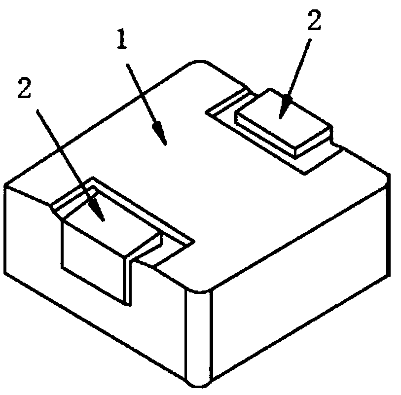
[0028] see figure 1 , an integrated inductor, comprising an inductance body 1, a coil embedded in the inductance body 1, a wire copper frame, and a wire terminal 2, and the wire terminal 2 is connected to the coil.

[0029] The manufacturing method of the above-mentioned integrated inductor includes the following steps:

[0030] Step A, making the iron core annular object, specifically: solidifying and sintering the mixed powder to obtain the iron core annular object, wherein: the mixed powder includes the following raw materials in parts by mass: 55.46 parts of carbonyl iron powder , 34.2 parts of reduced powder, 2.96 parts of magnesium oxide powder, 0.036 part of copper oxide powder, 0.65 part of stone powder and 6.20 parts of iron-based alloy; ) at a temperature of 850°C for 5.2 hours;

[0031] Step B, put the iron core annular object obtained in step A into a polishing machine for grinding, and obtain powder particles with a particle size of no more than 200 mesh, wherei...


PUM

PropertyMeasurementUnit
particle size (mesh)aaaaaaaaaa

Abstract

The invention provides a manufacturing method of an integrated inductor; the manufacturing method is simplified in technology and controllable in technological parameters, and can be used for obtaining high-quality products. The manufacturing method comprises the following steps: A. manufacturing an iron core ring-shaped object; B. putting the iron core ring-shaped object obtained in the step A into a polishing machine for grinding to obtain powder particles with particle sizes not exceeding 200 meshes; C. carrying out oxidization and insulation treatment to obtain oxidized and insulated powder; D. obtaining a mixture; E. putting a coil and a lead copper frame into a mould; pouring the mixture obtained in the step D into the mould for pressure casting to obtain an integrated structure; F. baking the integrated structure obtained in the step E, and then cooling to obtain a baked product; G. putting the baked product obtained in the step F into a passivation solution for passivating, and then carrying out aftertreatment on the passivated product to obtain the integrated inductor. The invention also discloses the integrated inductor manufactured by the method; the product is good in performances and less in damage to the manufacturing mould.

Description

technical field [0001] The invention relates to the technical field of inductors, in particular to a method for manufacturing an integrated inductor and the integrated inductor obtained by the method. Background technique [0002] Inductor products are mainly divided into three categories: first, electromagnetic interference processing inductors; second, signal processing inductors; third, power inductors. [0003] The operating voltage of general consumer electronic products is low-voltage DC. After obtaining the AC power provided by the power company, electronic products need rectification and transformation to obtain the required DC and lower voltage power for circuit operation. The impedance is proportional to the product of the frequency and the inductance value, and the inductance value is proportional to the square of the number of turns and the cross-sectional area of ​​the magnetic circuit. The work and operation of the circuit must obtain the required impedance for...

Claims


Application Information

Patent Timeline
Patent Type & Authority Patents(China)
IPC IPC(8): H01F41/00H01F41/02H01F1/42H01F17/04
CPCH01F1/42H01F17/04H01F41/00H01F41/0246H01F2017/048
Inventor 梁晓斌张兵潘锴
Owner SHENZHEN GUDIAN ELECTRONICS
Learn More