
Automobile electronic control unit voltage reduction power circuit

A technology of regulated power supply circuit and control unit, which is applied in the direction of conversion equipment without intermediate conversion to AC, and can solve problems such as low single failure rate, inability to diagnose and power off, and increased circuit complexity.

Inactive Publication Date: 2019-06-07
ISOFT INFRASTRUCTURE SOFTWARE
View PDF4 Cites 0 Cited by
  • Summary
  • Abstract
  • Description
  • Claims
  • Application Information

AI Technical Summary

Problems solved by technology

With the increasing degree of automation of automotive electronics, more and more ECUs are involved in automotive parts, and the complexity of circuits has also increased sharply. Automotive electronics have high requirements for the reliability of circuit hardware, and ECUs The components used in the ECU have specific requirements. The single failure rate of these components in various environments in the life cycle is lower than that of ordinary civil components, but it is still impossible to guarantee that all products of a certain ECU will be 100% safe in the entire product life cycle. If there is any problem; the interior of the car is generally powered by 12V or 24V, and the logic chips inside the various electronic control units (ECUs) of the car almost all need 5V or 3.3V DC voltage power supply, which requires a voltage-regulated power supply The circuit processes the 12V or 24V power supply connected to the ECU into 5V or 3.3V; but the most common step-down circuit on the market is a step-down circuit and it is irreversible, and cannot be diagnosed and powered off

Method used


Image

  • Automobile electronic control unit voltage reduction power circuit

Examples


Embodiment Construction

[0021] The following will clearly and completely describe the technical solutions in the embodiments of the present invention with reference to the accompanying drawings in the embodiments of the present invention. Obviously, the described embodiments are only some, not all, embodiments of the present invention. Based on the embodiments of the present invention, all other embodiments obtained by persons of ordinary skill in the art without creative efforts fall within the protection scope of the present invention.

[0022] It should be noted that, in the case of no conflict, the embodiments of the present invention and the features in the embodiments can be combined with each other.

[0023] The present invention will be further described below in conjunction with the accompanying drawings and specific embodiments, but not as a limitation of the present invention.

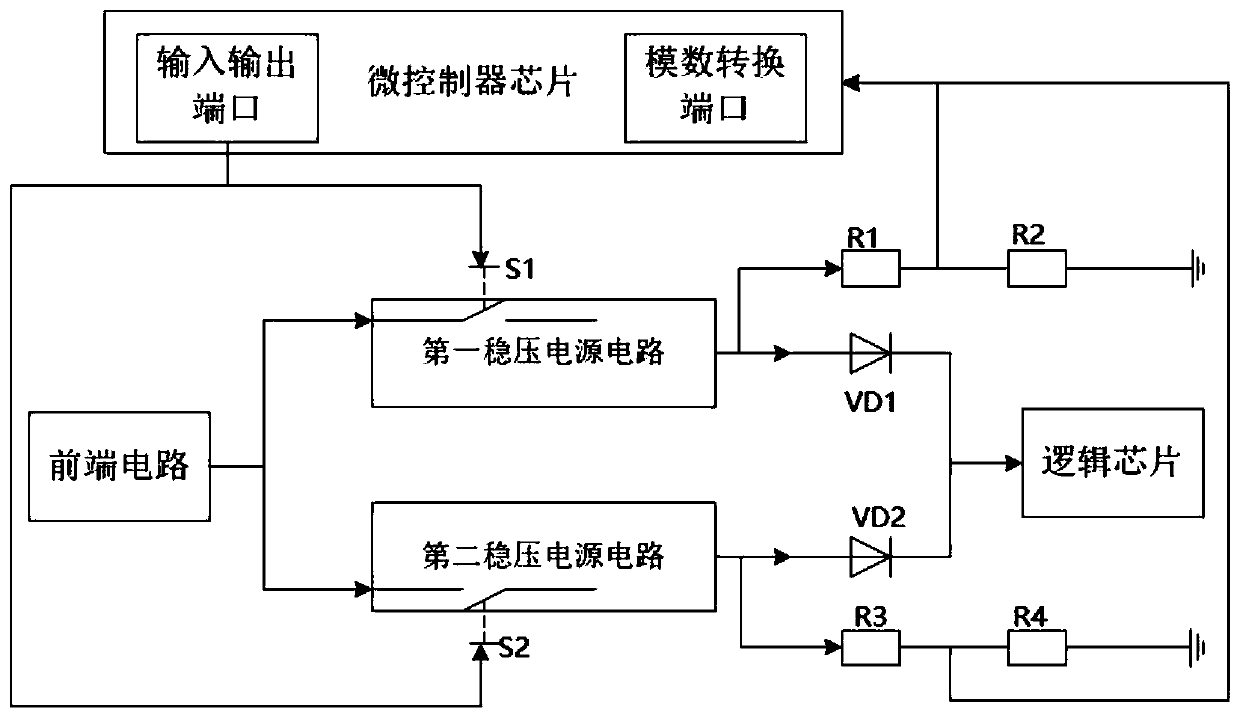
[0024] like figure 1 As shown, a step-down power supply circuit for an automotive electronic control unit, incl...


PUM


Abstract

The present invention relates to an automobile electronic control unit voltage reduction power circuit. The circuit comprises: a first voltage-stabilized source circuit connected with a front end circuit of an automobile electronic control unit and configured to output a voltage under the action of a first enabling signal; a second voltage-stabilized source circuit connected with the front end circuit of the automobile electronic control unit and configured to output a voltage under the action of a second enabling signal; a first resistance voltage division circuit connected with the first voltage-stabilized source circuit; a second resistance voltage division circuit connected with the second voltage-stabilized source circuit; a micro-controller chip connected with the first voltage-stabilized source circuit to output the first enabling signal and connected with the second voltage-stabilized source circuit to output the second enabling signal; a first analog-digital conversion port connected with a voltage division node of the first resistance voltage division circuit; and a second analog-digital conversion port connected with a voltage division node of the second resistance voltage division circuit. According to the automobile electronic control unit voltage reduction power circuit, the micro-controller chip can timely detect the faults of local power supply branches, and a message is generated and sent to an automobile communication bus.

Description

technical field [0001] The invention relates to the field of electronic control units, in particular to a step-down power supply circuit of an automotive electronic control unit. Background technique [0002] ECU (electronic control unit) is an electronic control unit, which generally refers to all electronic control systems on a car. It is composed of three parts: input circuit, microcomputer and output circuit. With the increasing degree of automation of automotive electronics, more and more ECUs are involved in automotive parts, and the complexity of circuits has also increased sharply. Automotive electronics have high requirements for the reliability of circuit hardware, and ECUs The components used in the ECU have specific requirements. The single failure rate of these components in various environments in the life cycle is lower than that of ordinary civil components, but it is still impossible to guarantee that all products of a certain ECU will be 100% safe in the en...

Claims


Application Information

Patent Timeline
IPC IPC(8): H02M3/04
Inventor 袁莱张晓先王琴李文龙王伟
Owner ISOFT INFRASTRUCTURE SOFTWARE
Learn More