Loudspeaker device

A speaker and monomer technology, applied in the field of electro-acoustic conversion, can solve the problems of waterproof failure of the speaker device, unable to completely fill the gap between the side surface of the monomer and the cover plate, etc., and achieve the effect of improving the waterproof yield and waterproof reliability.

Active Publication Date: 2019-06-07
AAC ACOUSTIC TECH (SHENZHEN) CO LTD
View PDF12 Cites 4 Cited by
  • Summary
  • Abstract
  • Description
  • Claims
  • Application Information

AI Technical Summary

Problems solved by technology

[0004] The purpose of the present invention is to provide a speaker device, aiming to solve the technical problem that the gap between the side of the cell and the cover plate cannot be completely filled when the side of the cell is glued, which eventually leads to the waterproof failure of the speaker device

Method used


Image

  • Loudspeaker device
  • Loudspeaker device
  • Loudspeaker device

Examples


Embodiment 1

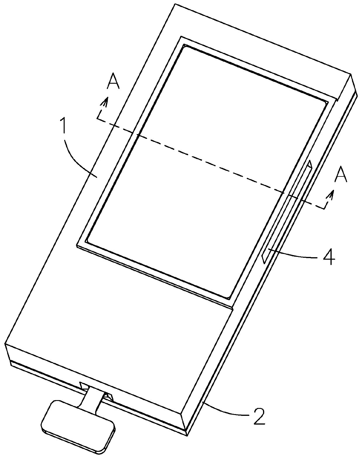
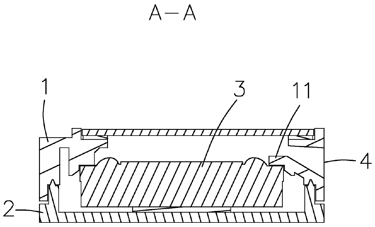
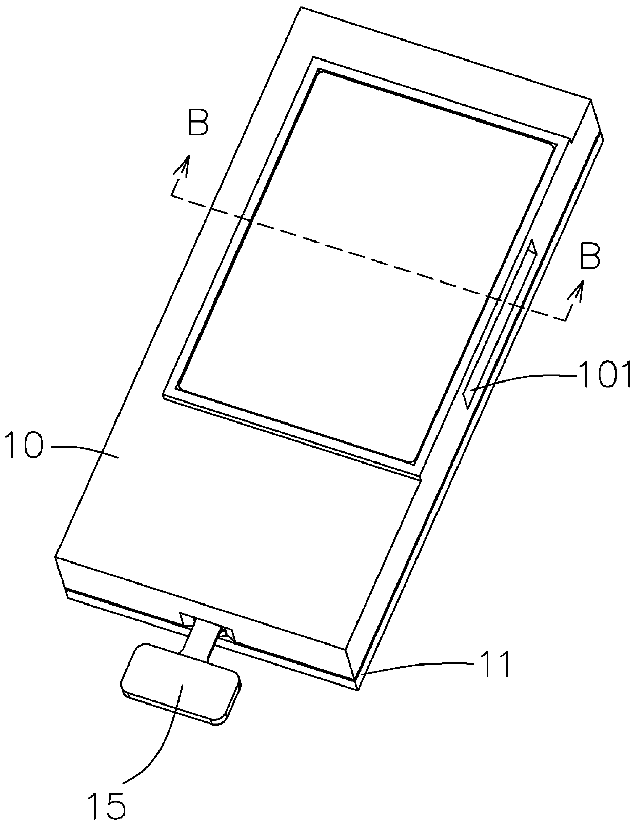
[0024] Such as Figure 3-Figure 7 As shown, a speaker device includes an upper cover 10, a lower cover 11 and a sounding unit 12, the upper cover 10 and the lower cover 11 are fixedly connected to form a receiving cavity 20, and the sounding unit 12 is installed on In the accommodating chamber 20, the upper cover 10 is provided with a sound outlet 101 and a support beam 102 is extended from the upper cover 10 toward the sound emitting unit 12, and the sound outlet 101 passes through the sound outlet channel and The accommodating cavity 20 is connected, the support beam 102 includes adjacent first surfaces 1021 and second surfaces 1022, and the sound emitting unit 12 includes a first end surface 121 close to the upper cover 10 and a first end surface close to the sound outlet. 101 and the second end surface 122 adjacent to the first end surface 121, the first surface 1021 is opposite to the first end surface 121 and sealed by filling the first adhesive 13 to form a first waterp...

Embodiment 2

[0031] The difference between this embodiment and Embodiment 1 lies in that a positioning structure is also provided between the upper cover 10 and the sound emitting unit 12 . The setting of the positioning structure can make the sound emitting unit 12 be installed into the accommodation cavity 20 more conveniently.

[0032] In this embodiment, the positioning structure includes a positioning column 16 and a positioning groove 17, and the positioning column 16 and the positioning groove 17 are interchangeably arranged on the upper cover 10 and the sound emitting unit 12, namely The positioning post 16 is arranged on the upper cover 10, and the positioning groove 17 is arranged on the sound emitting unit 12; or the positioning post 16 is arranged on the sound emitting unit 12, and the positioning groove 17 It is arranged on the upper cover 10 . In this embodiment, the positioning post 16 and the positioning groove 17 are mated through insertion.


PUM


Abstract

The invention provides a loudspeaker device. The loudspeaker device includes an upper cover, a lower cover and a sound production monomer; the supporting beam comprises a first surface and a second surface which are adjacent; The sounding unit comprises a first end face close to the upper cover and the second end surface close to the sound outlet and adjacent to the first end surface; a first adhesive is filled between the first end surface and the second end surface for gluing and sealing to form a first waterproof structure; the second surface is opposite to the second end surface; the jointof the first surface and the second surface is sunken towards the direction far away from the sound production monomer to form an air storage groove, a second adhesive is filled between the second surface and the second end surface, and the second adhesive permeates into the air storage groove to be glued and sealed so as to form blocked air which is stored in the air storage groove when a secondwaterproof structure is formed. When the first waterproof barrier on the front surface between the single voice diaphragm surface and the cover plate fails, the second waterproof structure can play awaterproof role, so that the waterproof yield and the waterproof reliability of the loudspeaker device are greatly improved.

Description

【Technical field】 [0001] The invention relates to the technical field of electroacoustic conversion, in particular to a loudspeaker device. 【Background technique】 [0002] With the advent of the mobile Internet era, the number of smart mobile devices continues to increase, and loudspeaker devices for playing sound are also widely used in current smart mobile devices. [0003] However, existing loudspeaker devices have the disadvantage of poor waterproofness. as attached figure 1 And attached figure 2 As shown, it is an existing loudspeaker device, which includes a top cover 1, a bottom cover 2 that is combined with the top cover 1 to form a storage space, a sound emitting unit 3 that is accommodated in the storage space, and the top cover 1 A support beam 11 is provided near the sound hole 4 , and the shape of the monomer 3 is positioned in cooperation with the upper cover 1 . When gluing the side of the monomer 3, the gap between the side of the monomer 3 and the cover...

Claims


Application Information

Patent Timeline
Patent Type & Authority Applications(China)
IPC IPC(8): H04R9/06H04R9/02
Inventor 童迪江时阳
Owner AAC ACOUSTIC TECH (SHENZHEN) CO LTD
Why Eureka
Try Eureka