
Double-bucket type solid-liquid separator and separation method

A solid-liquid separator, solid-liquid separation technology, applied in the direction of presses, manufacturing tools, etc., can solve problems such as reduced work efficiency, and achieve the effect of improving work efficiency and increasing the speed of juice discharge

Pending Publication Date: 2019-06-11
诸城市恒滨机械有限公司
View PDF0 Cites 1 Cited by
  • Summary
  • Abstract
  • Description
  • Claims
  • Application Information

AI Technical Summary

Problems solved by technology

[0004] The purpose of the embodiments of the present invention is to provide a double-barrel solid-liquid separator and a separation method to solve the problem of reduced work efficiency caused by waiting between various links in the existing pressing process

Method used


Image

  • Double-bucket type solid-liquid separator and separation method
  • Double-bucket type solid-liquid separator and separation method
  • Double-bucket type solid-liquid separator and separation method

Examples


Embodiment 1

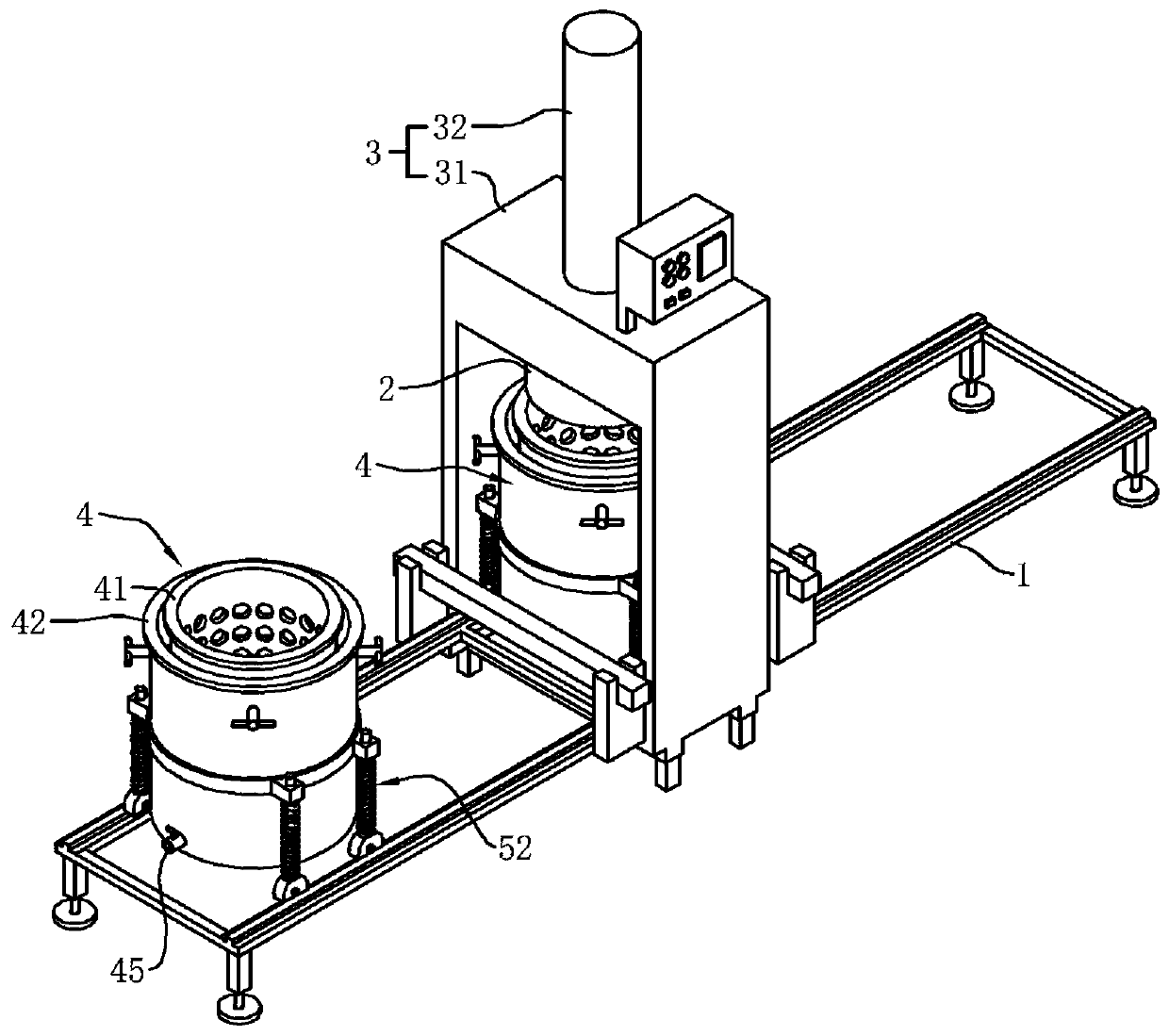
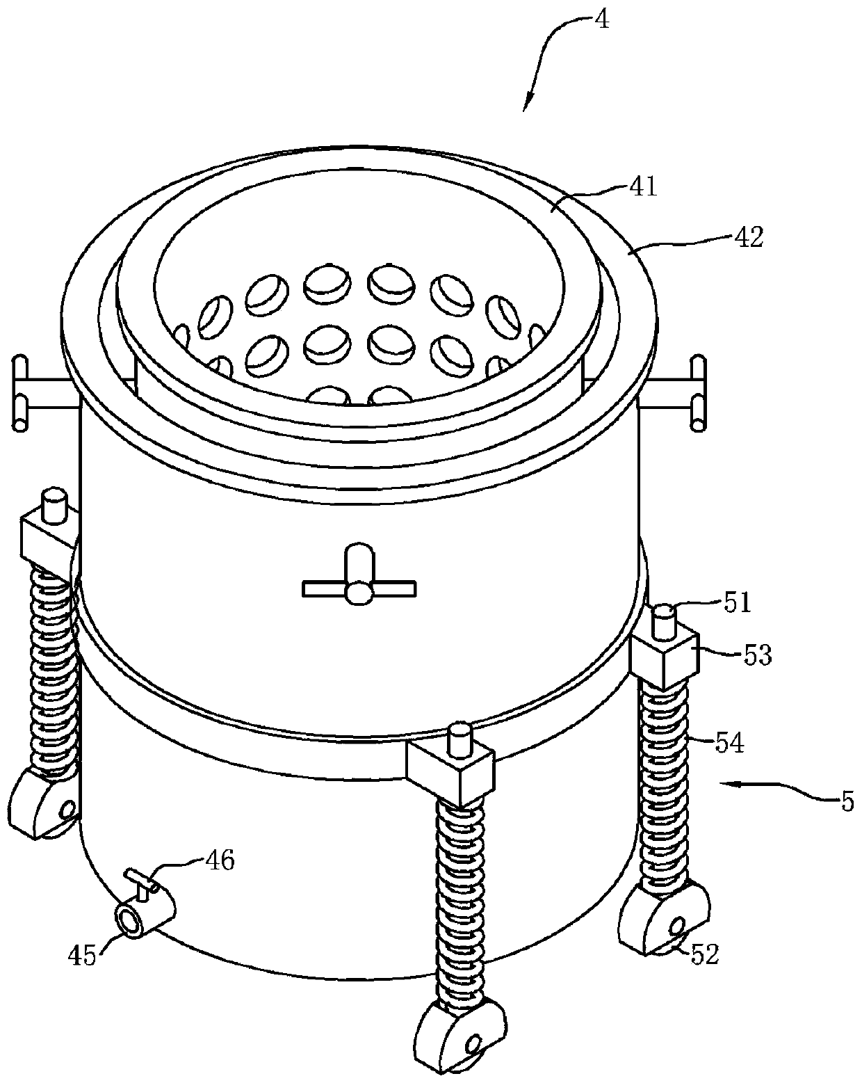
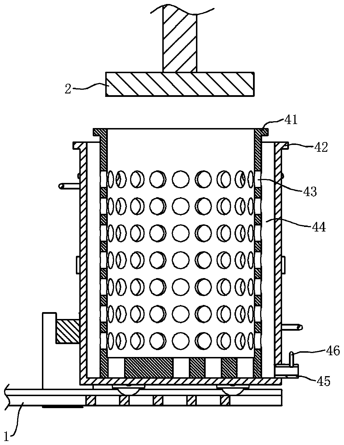
[0045] A double-barrel solid-liquid separator, such as figure 1 As shown, it includes a guide rail 1, a pressing plate 2, an extrusion device 3 and a barrel 4; the extrusion device 3 is located above the guide rail 1, and the barrel 4 is slidably connected with the guide rail 1. After the barrel 4 slides along the guide rail 1, the pressing plate 2 can be connected to the The barrel openings of the material barrel 4 are aligned or staggered along the moving direction of the pressure plate 2; the material barrel 4 has two, the material barrel 4 includes an inner barrel 41 and an outer barrel 42, and the inner barrel 41 is socketed inside the outer barrel 42; figure 2 and image 3 , the wall of the inner barrel 41 is provided with a solid-liquid separation hole 43, and there is a gap 44 between the outer wall of the inner barrel 41 and the inner wall of the outer barrel 42; The internal space of 42 is connected; the discharge pipe 45 is rotatably connected with a valve 46, and...

Embodiment 2

[0060] A separation method such as Figure 7 shown, including the following steps:

[0061] S1: Position initialization, move bucket A and bucket B along the guide rail 1 to the two ends of the guide rail 1 in the direction away from each other;

[0062] S2: Feed material in barrel A, put materials into barrel A;

[0063] S3: barrel A is pressed, barrel B is fed, and barrel A is moved to directly below the pressing plate 2, and the driving device 32 starts to work to drive the pressing plate 2 to squeeze the material in barrel A, and at the same time put the material into barrel B;

[0064] S4: Press barrel B, discharge and feed barrel A, remove the pressed barrel A from the bottom of platen 2 and move to the end of guide rail 1, discharge the slag in barrel A and start feeding, and move barrel B to the Directly below the pressing plate 2, the driving device 32 starts to drive the pressing plate 2 to squeeze the material in the barrel B;

[0065] S5: A barrel is squeezed, B...


PUM


Abstract

The invention discloses a double-bucket type solid-liquid separator and a separation method. The double-bucket type solid-liquid separator comprises a guide rail, a pressing plate, an extruding deviceand charging buckets, wherein the extruding device is located above the guide rail; the charging buckets are slidably connected with the guide rail; after the charging buckets slide along the guide rail, the pressing plate can align at or be staggered with the openings of the charging buckets along the movement direction of the pressing plate; the two charging buckets are arranged and comprise inner buckets and outer buckets; the inner buckets are sleeved in the outer buckets; solid-liquid separation holes are formed in the bucket walls of the inner buckets; gaps are arranged between the outer walls of the inner buckets and the inner walls of the outer buckets; the outer buckets are provided with drainage pipes; the drainage pipes communicate with the inner spaces of the outer buckets; and valves are rotatably connected onto the drainage pipes and are used for manually rotatably controlling the opening and the closing of the drainage pipes. The double-bucket type solid-liquid separator and the separation method have the advantages that the to-be-waiting time or the waiting time is shortened during the feeding, squeezing and discharging processes, so that the working efficiency isimproved.

Description

technical field [0001] The invention relates to the technical field of solid-liquid separation, in particular to a double-barrel solid-liquid separator and a separation method. Background technique [0002] Double-barrel solid-liquid separator is a kind of equipment used to squeeze and dehydrate the material containing juice to separate the juice in the material. [0003] Usually, the double-barrel solid-liquid separator includes a pressure plate and a material barrel. The material is stored in the material barrel. The pressure plate moves from the mouth of the material barrel to the bottom of the material barrel to squeeze the material in the material barrel and separate the juice in the material. ; But in the whole working process of the existing solid-liquid separator, feed into the barrel first, then squeeze, wait for the squeeze to be completed, then discharge, wait for the discharge to complete, then feed, wait for the feed to complete, then squeeze, so Circulation, i...

Claims


Application Information

Patent Timeline
IPC IPC(8): B30B9/06B30B9/26B30B15/30B30B15/32
Inventor 王胜利
Owner 诸城市恒滨机械有限公司
Learn More