
Turret leveling device for special vehicle for high-altitude operations

A technology for high-altitude operation and leveling device, applied in cranes and other directions, can solve the problems of complex device, poor carrying capacity and low precision of the adjustment device, and achieve the effects of low cost, strong carrying capacity and high adjustment accuracy

Pending Publication Date: 2019-06-11
HUBEI INST OF SPECIALTY VEHICLE
View PDF6 Cites 3 Cited by
  • Summary
  • Abstract
  • Description
  • Claims
  • Application Information

AI Technical Summary

Problems solved by technology

Because it takes one point as the reference point, and the adjustment trajectory of the other two points is a spherical surface, the two-point leveling method generally requires the use of universal hinges, and the carrying capacity of the adjustment device is poor; when multiple planar mechanisms are combined to drive a single point, the device more complex and less accurate

Method used


Image

  • Turret leveling device for special vehicle for high-altitude operations
  • Turret leveling device for special vehicle for high-altitude operations
  • Turret leveling device for special vehicle for high-altitude operations

Examples


Embodiment 1

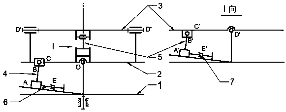
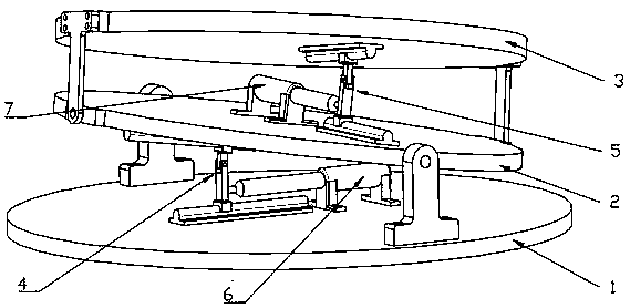
[0026] A special vehicle turret leveling device for aerial work, figure 1 Its structural principle diagram, figure 2 A schematic diagram of its structure. The turret leveling device is installed on the frame turret 1 and consists of a lower plate 2 with a rotating shaft D, an upper plate 3 with a rotating shaft D' and its rotating actuators stacked up and down. Wherein, the rotation axis D' of the upper plate 3 is parallel to the top surface of the lower plate 2, the rotation axis D of the lower plate 2 is parallel to the top surface of the frame turret 1, and the rotation axis D of the lower plate 2 is parallel to the rotation axis D' of the upper plate 3. It is arranged at a vertical staggered angle; the rotating actuator 4 of the lower plate 2 around the rotating axis D is a double-slider four-bar mechanism ABCD, and the rotating actuator 5 of the upper plate 3 around the rotating axis D' is a double-slider four-bar mechanism A'B'C 'D', the sliders at A and A' are active...

Embodiment 2

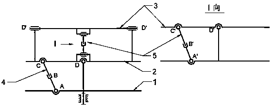
[0029] The structural schematic diagram of the turret leveling device using the swing cylinder four-bar mechanism is as follows image 3 shown, is figure 1 and figure 2 The leveling device shown is a simplified construction. image 3 The rotary actuators 4 and 5 shown are swing cylinder four-bar mechanisms, which are replaced by swing cylinders ABC and A'B'C' respectively figure 1 and figure 2 The dual slider widget in . Since the swing cylinder is the original moving component and is a linear actuator, it can be realized directly by using a hydraulic cylinder, a linear motor or a lead screw and nut pair according to the conditions of the power source. The leveling device adopting the swing cylinder four-bar mechanism has simpler structure and lower cost.

Embodiment 3

[0031] figure 1 In addition to hydraulic cylinders, other types of linear actuators such as air cylinders, linear motors, screw nut pairs, etc. can also be used for the driving elements 6 and 7 shown in , depending on the application conditions.


PUM


Abstract

The invention discloses a turret leveling device for a special vehicle for high-altitude operations, and relates to the special vehicle for the high-altitude operations. The turret leveling device comprises two layers of flat plates and rotating actuators of the flat plates; the flat plates are mounted on a frame turret, are stacked up and down and comprise rotating shafts; the rotating shaft of the upper-layer flat plate is parallel with the top surface of the lower-layer flat plate; the rotating shaft of the lower-layer flat plate is parallel with the top surface of the turret; the rotatingshafts of the two layers of flat plates are arranged at an perpendicularly staggered angle; and each rotating actuator is a double-slider four-rod mechanism, and sliders of the rotating actuator are driving components and are driven by a hydraulic cylinder to move linearly. According to the turret leveling device, the two layers of flat plates are rotated, so that rolling and pitch attitude adjustment of the upper-layer flat plate is realized, and the purpose of turret leveling is achieved. The leveling device has the advantages of high carrying capacity, large leveling angle range, quick dynamic response, high precision, high stability, safety, reliability and the like and is applicable to static and dynamic turret leveling for the special vehicle which is used for the high-altitude operations and is high in mobility and high in site adaptability.

Description

technical field [0001] The invention relates to a turret leveling device for a special vehicle for high-altitude work, and relates to a special vehicle for high-altitude work. Background technique [0002] Special vehicles for high-altitude operations are widely used in the fields of construction and maintenance of large facilities, fire protection and rescue of high-rise buildings. With the advancement of technology, special vehicles for aerial work have achieved rapid development in terms of boom lifting height and operational mobility, but it also brings problems in vehicle stability and structural safety. [0003] The current domestic and foreign requirements for high-altitude operation vehicles require that the outriggers should have manual or automatic frame leveling capabilities at an angle of 5-8° to meet the parking needs of various work sites. In particular, in the technology of aerial ladder fire fighting and rescue vehicles, due to the poor anti-distortion and d...

Claims


Application Information

Patent Timeline
Patent Type & Authority Applications(China)
IPC IPC(8): B66C23/62B66C23/78B66C23/80B66C23/36
Inventor 程远雄黄其柏陆仕航
Owner HUBEI INST OF SPECIALTY VEHICLE
Learn More