Hardware switch

A switch and hardware technology, applied in the field of hardware switches, can solve the problems of increasing the construction cost and storage cost of objects, and the change of the location of the equipment cannot be matched as a whole, so as to achieve the effect of low construction cost and small wall capacity.

Inactive Publication Date: 2019-06-11
西安大富宇航科技有限公司
View PDF0 Cites 0 Cited by
  • Summary
  • Abstract
  • Description
  • Claims
  • Application Information

AI Technical Summary

Problems solved by technology

[0002] The cover of the current hardware switch is equipped with a wire post cover and a wall piece used to cover the wire post. The wall piece, the wire post cover and the cover body are often stamped and formed as a whole. In addition, the wire post cover must be the same as the wire post on the PCB board. Face to face, the wall pieces face to face with the contacts on the PCB board, and the stamped cover cannot be matched as a whole when the

Method used


Image

  • Hardware switch
  • Hardware switch

Examples


Embodiment Construction

[0011] The present invention will be further described below in conjunction with examples.

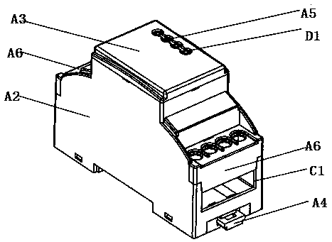
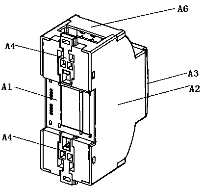
[0012] Such as Figure 1-Figure 2 As shown, the hardware switch of this embodiment includes a support plate A1, a cover body A2, a wall piece A3 and a PCB board, the cover body A2 is equipped on the support plate A1, the wall piece A3 is covered on the cover body A2, and the PCB board is equipped on the On the support plate A1 in the cover body A2, the two ends of the PCB board respectively form a line post, and the top and bottom ends of the outer side wall of the support plate A1 are equipped with locking pieces A4, and the locking pieces A4 are connected to the support plate A1 through a spiral glass bronze wire. Extruded and connected, two pairs of lighting grooves D1 are formed on the wall piece A3, and the two pairs of lighting grooves D1 are distributed along the vertical direction.

[0013] The light guide groove D1 is equipped with a light bar A5, and the top and bottom ends o...


PUM


Abstract

A hardware switch comprises a support plate, a cover body, a wall piece and a PCB board, wherein the cover body is arranged on the support plate, the wall piece is shielded on the cover body, the PCBboard is arranged on the support plate in the cover body, both ends of the PCB board respectively form wire columns, both the top and bottom of the outer side wall of the support plate are provided with locking members that are pressed and connected with the support plate via the spiral glass bronze wire, and two pairs of guiding grooves are formed on the wall piece and distributed along the vertical direction. The hardware switch effectively avoids the defect of increased construction cost and storage cost of the object in the prior art.

Description

technical field [0001] The invention relates to the technical field of hardware and electromechanical technology, in particular to a hardware switch. Background technique [0002] The cover of the current hardware switch is equipped with a wire post cover and a wall piece used to cover the wire post. The wall piece, the wire post cover and the cover body are often stamped and formed as a whole. In addition, the wire post cover must be the same as the wire post on the PCB board. Face to face, the wall pieces face to face with the contacts on the PCB board, and the stamped cover cannot be matched as a whole when the parts of the PCB board are changed or moved, even if the position of the line post is often unable to change However, other components on the PCB will be changed depending on the location of the requirements. The stamped cover needs to replace all the covers, and another casting board must be built for the changed location. In addition, several PCB boards must Kee...

Claims


Application Information

Patent Timeline
IPC IPC(8): H01H9/02
Inventor 不公告发明人
Owner 西安大富宇航科技有限公司
Why Eureka
Try Eureka