Isolation switch rainproof cover

A technology of isolating switch and high-voltage isolating switch, applied in the direction of air switch components, etc., can solve the problems of large-scale power outage, box corrosion, economic loss, etc., achieve high secondary recovery rate, not easy to aging and fall off, and reduce construction difficulty Effect

Pending Publication Date: 2019-06-11
STATE GRID CORP OF CHINA +1
View PDF5 Cites 3 Cited by
  • Summary
  • Abstract
  • Description
  • Claims
  • Application Information

AI Technical Summary

Problems solved by technology

[0002] The high-voltage isolating switch (knife switch) is an important part of the power grid. It plays an important role in isolating the power supply, changing the operating mode of the system, and performing switching operations. However, the transmission link that provides the driving device for the knife switch runs through the mechanism box. Design defects of some manufacturers, poor sealing
Especially in the rainy season, it is not enough to ensure the tightness of the mechanism box. The existing problems are: 1. The design of the top cover of the box body is unreasonable. There is a sealing ring on the part where the connecting rod passes through the hole on the top cover of the mechanism box. After the sealing ring ages, there will be a gap between the rotating shaft of the transmission connecting rod. Penetrate into the mechanism box, causing the motor, gear, and other transmission parts inside the mechanism box to corrode and jam, causing the position of the knife switch to not correspond to the backstage and other faults; 3. The exposed sealing ring is easy to age and fall off, and dust and other particles are easy to enter the box and deposit on it for a long time The electrical unit will cause damage to the secondary components, short circuit between terminal blocks, and even refusal to open and close the knife switch, which will affect the switching operation and accident handling, causing delayed power supply to the society, and even large-scale power outages, resulting in huge economic losses.

Method used


Image

  • Isolation switch rainproof cover

Examples


Embodiment Construction

[0018] Below in conjunction with accompanying drawing, the present invention is described in further detail:

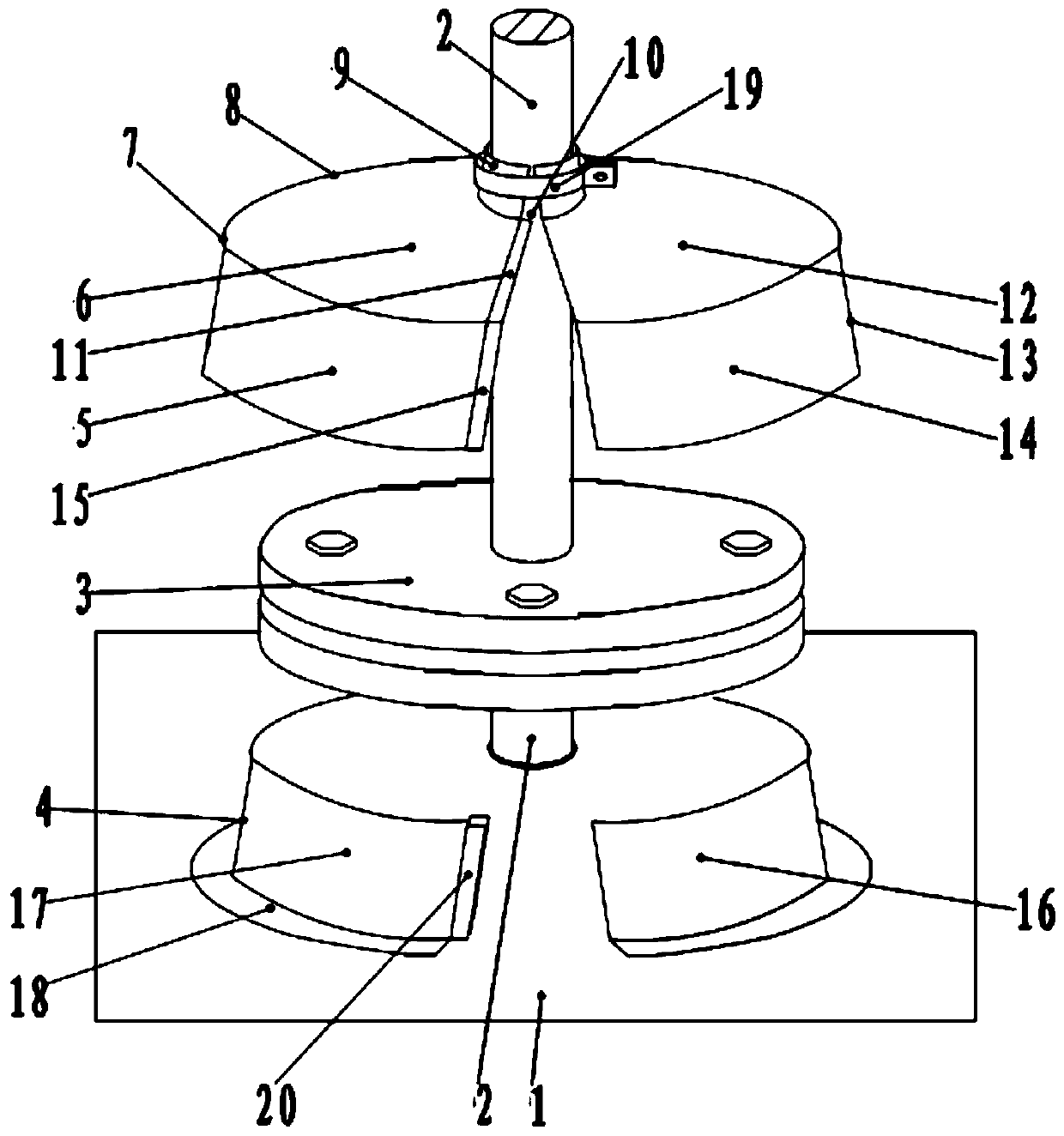
[0019] see figure 1 , the isolating switch rain cover of the present invention includes a transmission connecting rod 2 passing through the high-voltage isolating switch mechanism box 1 and a flange 3 on the transmission connecting rod 2, and a rainproof cover is arranged on the transmission connecting rod 2 above the flange 3. Cap 7, the diameter of the rainproof cap 7 is greater than that of the flange plate 3, and the rainproof cap 7 includes the rainproof cap body that the left and right parts can hug the transmission connecting rod 2. It includes an umbrella-shaped cap 8, a sleeve 9 and a lower skirt 13. The top of the umbrella-shaped cap 8 has an opening 10 communicating with the sleeve 9. The lower edge of the umbrella-shaped cap 8 is connected to the lower skirt 13. The umbrella-shaped cap 8 includes a first umbrella Type cap 6 and the second umbrella type ca...


PUM


Abstract

The invention discloses an isolation switch rainproof cover which comprises a transmission connection rod passing through a high-voltage isolation switch mechanism case and a flange plate on the transmission connection rod. A rainproof cap is arranged on the transmission connection rod above the flange plate; the rainproof cap comprises a rainproof cap body both left and right parts can hold the transmission connection rod the rainproof cap comprises an umbrella-shaped cap, a bushing and a lower skirt; the transmission connection rod passes through the bushing and the umbrella-shaped cap; therainproof cap is fixed on the transmission connection rod by a hoop to synchronously rotate; a sleeve is arranged on the transmission connection rod below the flange plate; and the sleeve is arrangedon the high-voltage isolation switch mechanism case. The isolation switch rainproof cover is ingenious in structure; in an up-and-down staggered mode, rainwater cannot be accumulated in a large area on a top cover of the high-voltage isolation switch mechanism case so as to avoid corrosion and jamming of a transmission part, which are caused by rainwater pouring, and prolong the service life of arubber material sealing part; the spliced structure adopts a combined mode so as to facilitate disassembling and assembling; a material secondary recovery rate is high; and the isolation switch rainproof cover is an efficient and reliable outdoor high-voltage electrical equipment protection device.

Description

technical field [0001] The invention relates to a protective device for outdoor high-voltage electrical equipment, in particular to a rainproof cover for an isolating switch. Background technique [0002] The high-voltage isolating switch (knife switch) is an important part of the power grid. It plays an important role in isolating the power supply, changing the operating mode of the system, and performing switching operations. However, the transmission link that provides the driving device for the knife switch runs through the mechanism box. Some manufacturers have design defects and poor sealing. Especially in the rainy season, it is not enough to ensure the tightness of the mechanism box. The existing problems are: 1. The design of the top cover of the box body is unreasonable. There is a sealing ring on the part where the connecting rod passes through the hole on the top cover of the mechanism box. After the sealing ring ages, there will be a gap between the rotating sh...

Claims


Application Information

Patent Timeline
Patent Type & Authority Applications(China)
IPC IPC(8): H01H31/02
Inventor 铁子甲王亚萍杨绪坤付涛独亚军连磊陈瑞雷学文韩鹍杨雷
Owner STATE GRID CORP OF CHINA
Why Eureka
Try Eureka