

Novel block type circle splicing welding machine for stator iron cores
A stator iron core and block type technology is applied in the field of new block type stator iron core round welding machines, which can solve the problems of affecting PCB board welding, difficult results, affecting the down-moving process, etc., to improve work efficiency and automation. The effect of high degree and shortening of production time
- Summary
- Abstract
- Description
- Claims
- Application Information
AI Technical Summary
Problems solved by technology
Method used
Image

Examples
Embodiment Construction
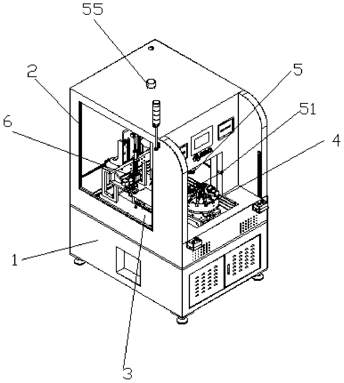
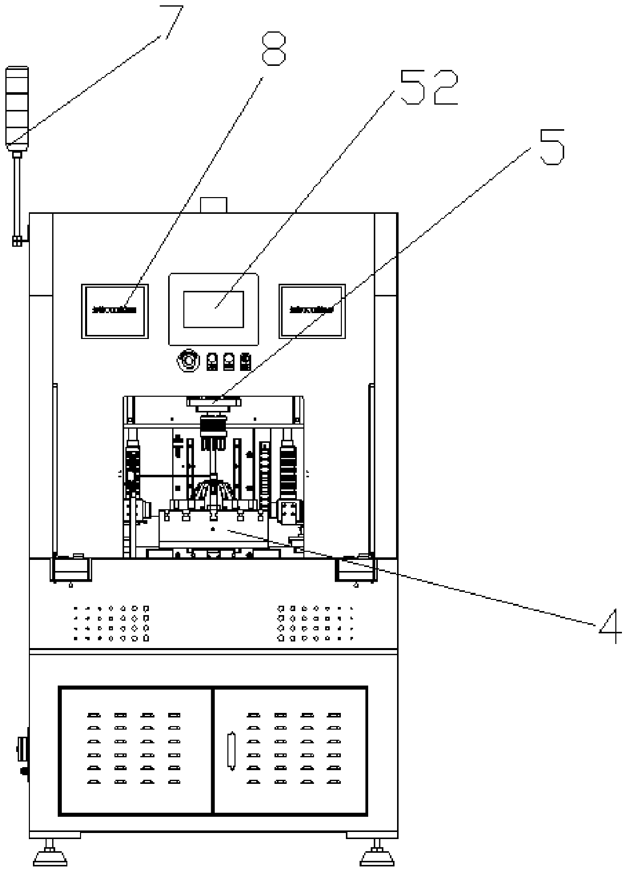
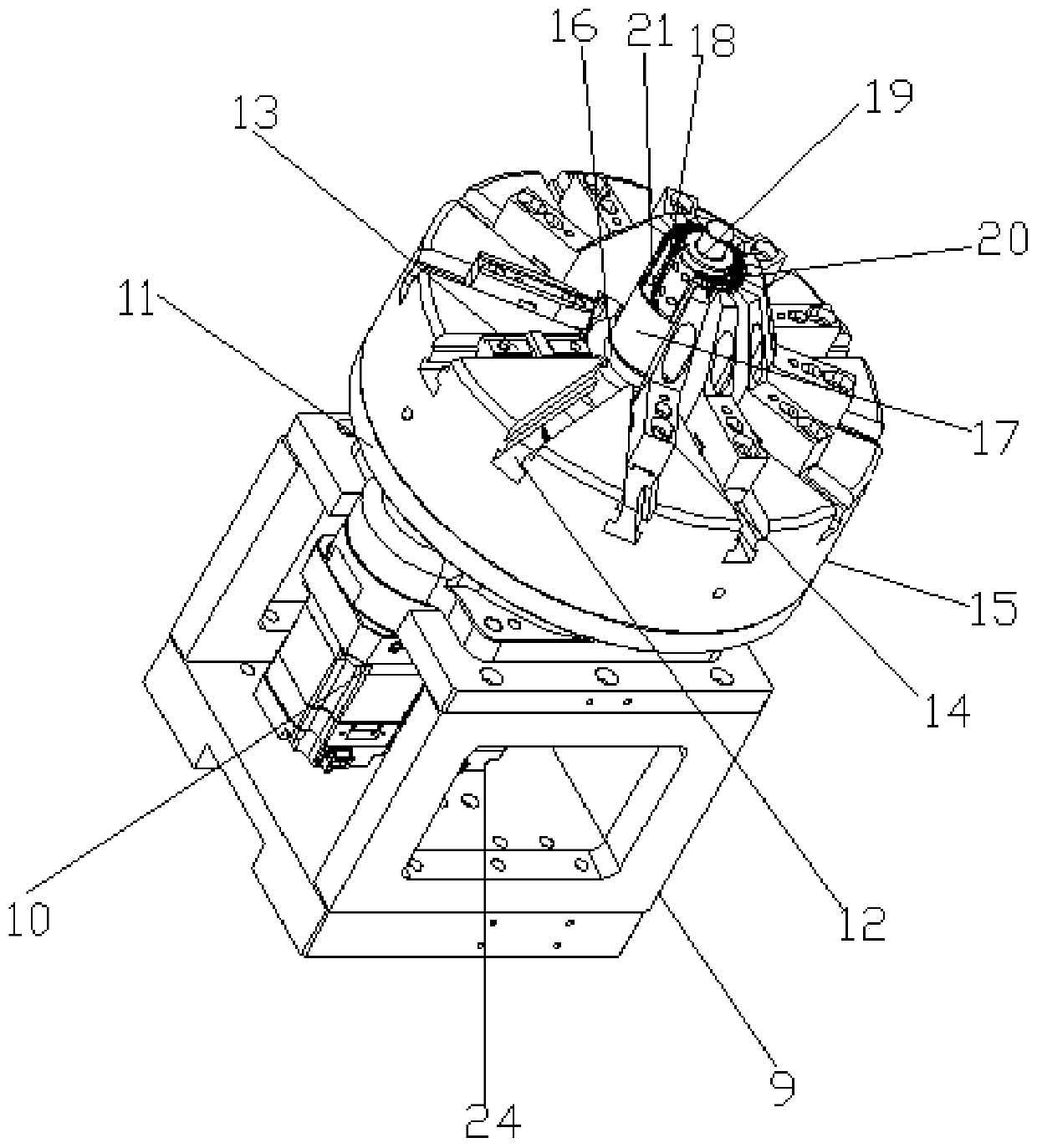
[0047] refer to Figure 1 to Figure 10 A new block-type stator core round welding machine is shown, including a chassis 1, a safety cover 2, a working table 3, a stator tightening mechanism 4, a stator end face shaping mechanism 5, a stator welding mechanism 6, an indicator light 7, The stator core 20, the control panel 52, and the worktable 3 are arranged on the chassis 1, and the chassis 1 and the safety cover 2 are connected as a whole, and the stator tightening mechanism 4, the stator end face shaping mechanism 5, and the stator welding mechanism 6 are all installed on the worktable 3, the control panel 52 controls the work of the stator tightening mechanism 4, the stator end face shaping mechanism 5, and the stator welding mechanism 6, and the two sides of the control panel 52 are provided with welding CCD windows 8, and the stator tightening mechanism 4 is used for multiple The stator core 20 is fixed, the stator end face shaping mechanism 5 is used to press the end face...
PUM
 Abstract
Description
Claims
Application Information