Check patentability & draft patents in minutes with Patsnap Eureka AI!

Vehicle Front Structure

A vehicle and structure technology, applied in the direction of vehicle components, substructure, superstructure, etc., can solve the problems of limited rigidity improvement, increased number of parts, high cost, etc., and achieve the effect of improving vibration characteristics and rigidity

Active Publication Date: 2021-08-31
SUZUKI MOTOR CORP
View PDF9 Cites 0 Cited by
  • Summary
  • Abstract
  • Description
  • Claims
  • Application Information

AI Technical Summary

Problems solved by technology

[0008] In addition, in the conventional vehicle front structure, the side reinforcement member is provided on the inner side of the fender, so there is a problem that the rigidity improvement of the vehicle front is limited, and the side reinforcement member is required. Leads to increased part count and high cost

Method used


Image

  • Vehicle Front Structure
  • Vehicle Front Structure
  • Vehicle Front Structure

Examples


Embodiment Construction

[0023] Hereinafter, the present invention will be described in detail based on the illustrated embodiments.

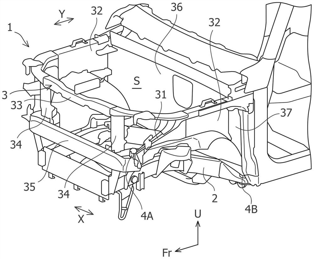
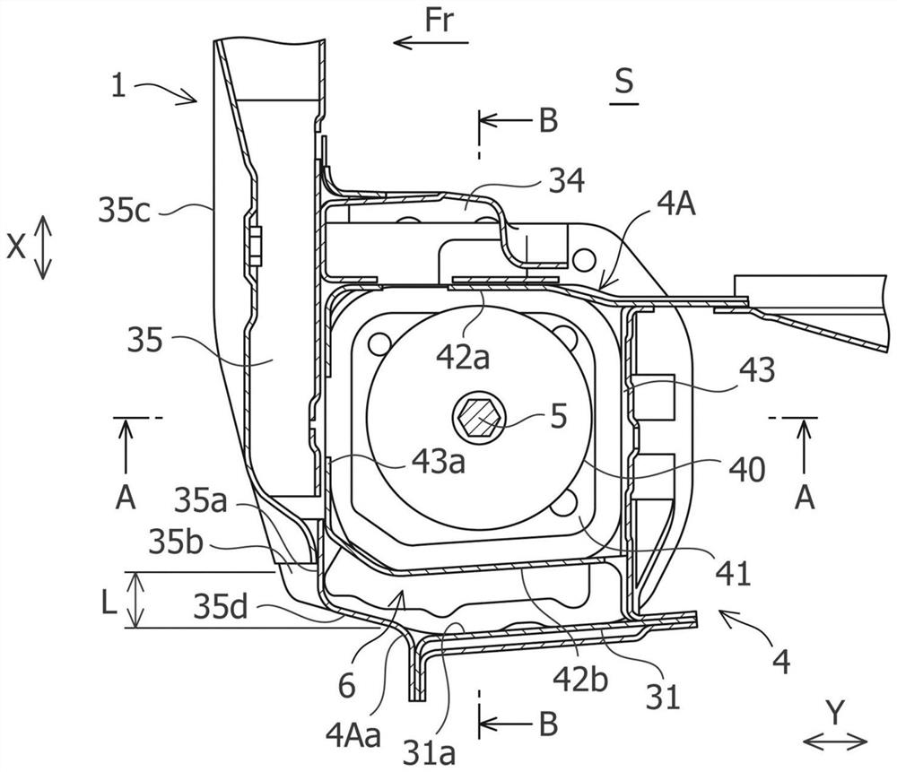
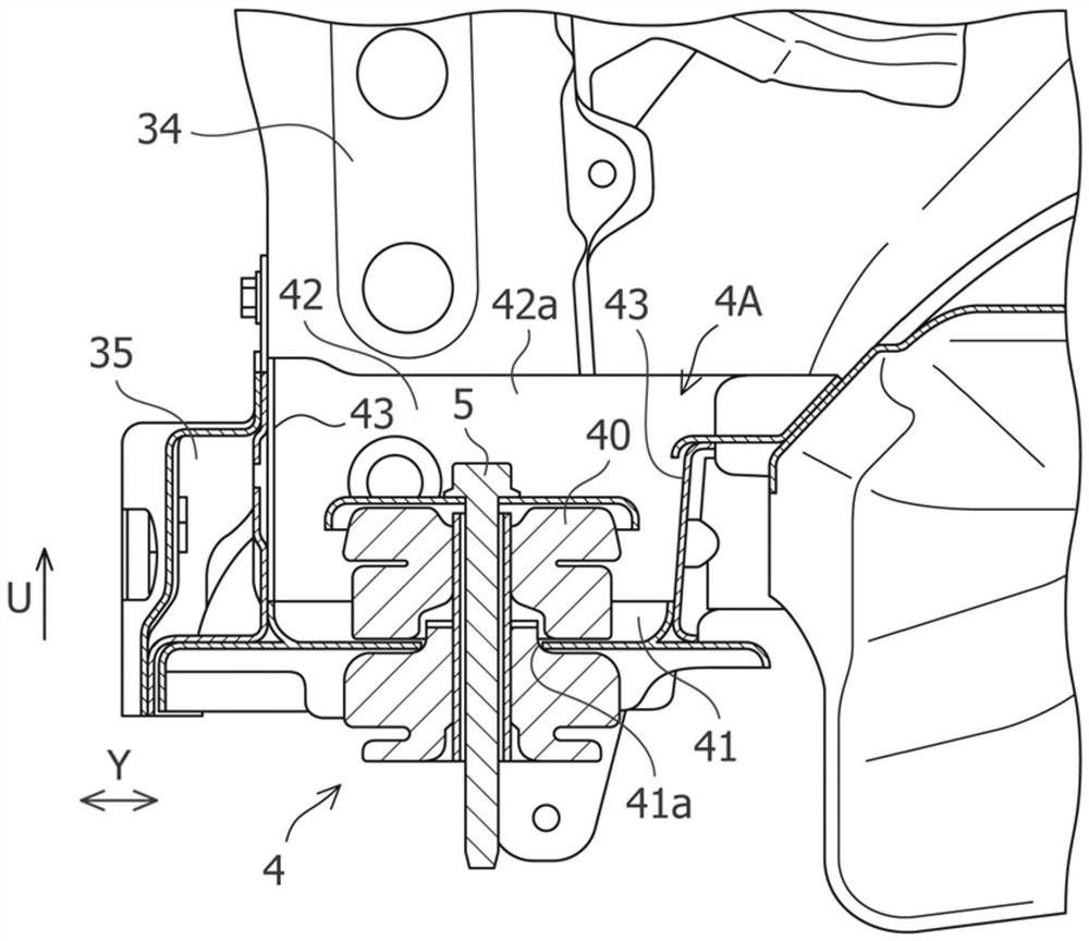
[0024] Figure 1 to Figure 4 It shows the structure of the vehicle front part which concerns on embodiment of this invention. In addition, in the drawings, the arrow Fr direction indicates the vehicle front, the arrow U direction indicates the vehicle upper direction, the arrow X direction indicates the vehicle width direction, and the arrow Y direction indicates the vehicle front-rear direction.

[0025] Such as figure 1 As shown, the vehicle front portion 1 to which the structure of the embodiment of the present invention is applied mainly includes chassis frames 2 extending in the vehicle front-rear direction and provided on the left and right sides in the vehicle width direction at the lower part of the power unit mounting space S, and provided on the left and right sides of the vehicle width direction. The power unit mounts the upper body 3 in the upper part of...


PUM


Abstract

The present invention provides a vehicle front structure capable of improving the rigidity of an upper body and a body mount fixing portion, improving the vibration characteristics of the vehicle front, and effectively distributing input to the body mount at the vehicle front . In the front structure of the vehicle, the upper body is fixed to the chassis frame by a body mount (40), and a body mount fixing portion (4) for fixing the body mount is disposed on the lower part of the upper body. The body mount fixing part (4) has: a mount fixing surface (41), which has a fixing hole for fixing the body mount (40); Extend; and the vertical wall portion (43), which is located in the front-rear direction of the mounting part fixing surface, and extends in the up-down direction, and the side wall portion is joined with a bracket member (34) of a closed cross-sectional shape extending in the up-down direction, and the vertical wall portion A beam (35) of closed cross-sectional shape extending in the width direction is joined.

Description

technical field [0001] The invention relates to a vehicle front structure. Background technique [0002] In the conventional vehicle front structure, a structure is known in which fenders are arranged on both sides of the front part of the vehicle body of the engine compartment, and a seal that cooperates with these fenders is provided on the inner side of the fenders. In the cross-sectional side reinforcement member, the front and rear end portions of the side reinforcement member are connected to the chassis frame via vehicle body mounting brackets (for example, refer to Patent Document 1). [0003] prior art literature [0004] patent documents [0005] Patent Document 1: Japanese Patent Application Laid-Open No. 7-267135 Contents of the invention [0006] The problem to be solved by the invention [0007] However, in the above-mentioned conventional vehicle front structure, the vehicle body and the chassis frame of the engine room portion are only connected by the...

Claims


Application Information

Patent Timeline
Patent Type & Authority Patents(China)
IPC IPC(8): B62D25/08
CPCB62D21/11B62D25/082B62D27/04
Inventor 大仓康平
Owner SUZUKI MOTOR CORP
Features
  • R&D
  • Intellectual Property
  • Life Sciences
  • Materials
  • Tech Scout
  • Unparalleled Data Quality
  • Higher Quality Content
  • 60% Fewer Hallucinations
Learn More