Method for measuring displacement of tamping device of railway track lifting and lining tamping vehicle contactlessly

A non-contact, measuring device technology, applied in the direction of measuring devices, optical devices, instruments, etc., can solve problems such as failure, loose mechanical parts of sensors, and decreased measurement accuracy of sensors, so as to achieve the effect of prolonging service life and saving measurement costs

Inactive Publication Date: 2019-06-14
长沙瀚鹏电子技术有限公司
View PDF7 Cites 0 Cited by
  • Summary
  • Abstract
  • Description
  • Claims
  • Application Information

AI Technical Summary

Problems solved by technology

[0004] The purpose of the present invention is to provide a non-contact method for measuring the displacement of the tamping device of the railway tamping vehicle, so as to solve the complex and precise internal mechanical structure of the existing sensor proposed in the background technology, and the tamping vehicle operation When the car body vibrates violently, it is easy to cause the internal mechanical parts of the sensor to loosen, resulting in a decrease in the measurement accuracy of the sensor or even complete failure. In addition, when the tamping vehicle is in operation, the tamping device must perform about 1300 reciprocating movements per hour, and the number of times the coil spring expands and contracts is limited, so the working life of this sensor is relatively short, and it needs to be replaced frequently

Method used


Image

  • Method for measuring displacement of tamping device of railway track lifting and lining tamping vehicle contactlessly
  • Method for measuring displacement of tamping device of railway track lifting and lining tamping vehicle contactlessly
  • Method for measuring displacement of tamping device of railway track lifting and lining tamping vehicle contactlessly

Examples


Embodiment Construction

[0026] The following will clearly and completely describe the technical solutions in the embodiments of the present invention with reference to the accompanying drawings in the embodiments of the present invention. Obviously, the described embodiments are only some, not all, embodiments of the present invention. Based on the embodiments of the present invention, all other embodiments obtained by persons of ordinary skill in the art without making creative efforts belong to the protection scope of the present invention.

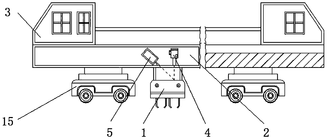
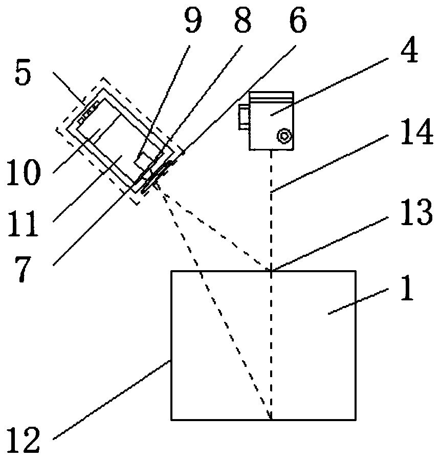
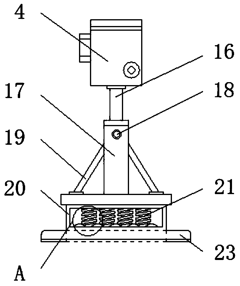
[0027] see Figure 1-5 , the present invention provides a technical solution: a non-contact method for measuring the displacement of a tamping device on a railway tamping vehicle, comprising a tamping device 1, a tamping vehicle girder 2, a tamping vehicle 3, and a laser transmitter 4 , CCD measuring device 5, optical lens 6, CCD sensor 7, image 8, displacement 9, signal output interface 10, algorithm module 11, actual displacement information 12, laser spot 1...


PUM


Abstract

The invention relates to a method for measuring displacement of a tamping device of a railway track lifting and lining tamping vehicle contactlessly. The method comprises the tamping device, a CCD sensor and a signal output interface. A tamping vehicle crossbeam is set at an upper end of the tamping device. The tamping vehicle is fixed at an exterior of the tamping vehicle crossbeam. A laser transmitter and a CCD measurement device are mounted at the upper end of the tamping vehicle crossbeam. An optical lens is set in the CCD measurement device. The CCD sensor is mounted at an upper side of the optical lens. An image is displayed at the upper end of the CCD sensor. According to the method for measuring the displacement of the tamping device of the railway track lifting and lining tampingvehicle contactlessly, the image corresponds to a position of the tamping device on the CCD sensor, a laser spot can be reflected to the optical lens of the CCD measurement device through utilizationof a surface of the tamping device and is imaged on the CCD sensor, the laser spot is incident on the CCD sensor to generate the image through the optical lens of the CCD measurement device, and vertical displacement can be computed through utilization of a relational expression between displacement and practical displacement.

Description

technical field [0001] The invention relates to the technical field of tamping vehicles, in particular to a non-contact method for measuring the displacement of a tamping device of a tamping vehicle on a railway uplift road. Background technique [0002] The tamping vehicle is a kind of large-scale road maintenance machinery (referred to as a large machine), which is suitable for the construction of new lines of railway lines, the maintenance of existing lines after large and medium repairs and screen cleaning operations, and the maintenance of operating lines. When the tamping vehicle is operating, the tamping device is Reciprocating up and down in the vertical direction. In order to ensure the quality of the work, the rising and falling position and position of the tamping device need to be precisely controlled. For this reason, it is necessary to accurately measure the displacement of the tamping device in real time. The current methods for measuring this displacement are ...

Claims


Application Information

Patent Timeline
Patent Type & Authority Applications(China)
IPC IPC(8): G01B11/02
CPCG01B11/02
Inventor 邹洪波
Owner 长沙瀚鹏电子技术有限公司
Why Eureka
Try Eureka