
Radio frequency emissions sensing system and method for the characterization of system operation

A sensing system, radio frequency transmission technology, applied in transmission systems, measurement devices, engine components, etc., can solve the problem of miscalculating the area of ​​interest state, limited operating window, etc.

Inactive Publication Date: 2019-06-14
CTS CORP ELKHART
View PDF11 Cites 0 Cited by
  • Summary
  • Abstract
  • Description
  • Claims
  • Application Information

AI Technical Summary

Problems solved by technology

These measurements associated with complex and complex algorithms often create a limited window of operation and / or the possibility of miscalculating regions of interest states

Method used


Image

  • Radio frequency emissions sensing system and method for the characterization of system operation
  • Radio frequency emissions sensing system and method for the characterization of system operation
  • Radio frequency emissions sensing system and method for the characterization of system operation

Examples


Embodiment Construction

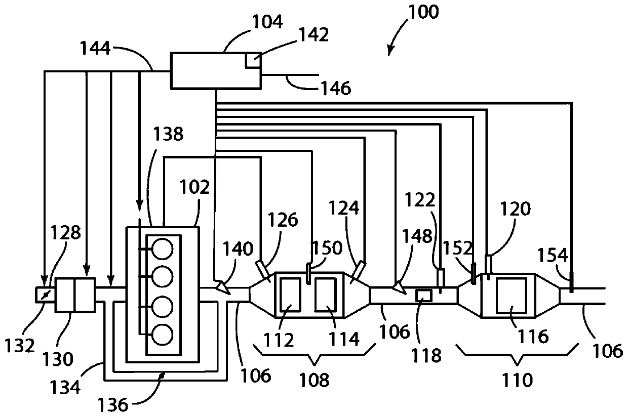
[0035] The present invention relates to a radio frequency (RF) sensor (antenna and RF electronics), engine and engine controller / aftertreatment controller, aftertreatment emissions sensing, measurement and control system 100 for an engine system consisting of an engine 102 and engine exhaust gas aftertreatment system including various catalysts, filters and auxiliary sensors, metering elements and pipelines. Accordingly, as described herein, the engine system refers to a combined engine and after-launch treatment system.

[0036] Although the use of the invention of this patent application is for RF sensing of automotive engine exhaust / emission systems, it should be understood that the principles and features of the invention are applicable to any device or process system, including but not limited to the following: , trucks, buses, construction equipment, agricultural equipment, generators, boats, locomotives, and the like. Additional possible applications include chemical p...


PUM


Abstract

An RF emissions sensing system including RF sensors for transmitting / receiving RF signals to and from engine system emission control components, a control unit for collecting / processing information from the RF signals and controlling system outputs. The RF emissions sensing system includes a means and method for the characterization of the operating state and / or performance of the engine system including the use of time-based or historical RF information and system outputs, the application / monitoring of pertubations to the engine system, the comparison of system outputs to baseline / reference system outputs, the periodic activation of the engine system after shut-down, the monitoring of changes in the electric or temperature profiles of the engine system emission control components, and communication with external sources to improve the accuracy of the system outputs.

Description

[0001] Cross References to Related Applications [0002] This patent application claims priority and benefit on the filing dates of and is a continuation-in-part of: U.S. Patent Application Serial No. 15 / 481,670 filed April 7, 2017; U.S. Patent Application Serial No. 15 / 461,128; U.S. Patent Application Serial No. 14 / 733,525, filed June 8, 2015; and U.S. Patent Application Serial No. 14 / 733,486, filed June 8, 2015, the disclosures and contents of which are All references in their entirety are expressly incorporated herein. [0003] This patent application also claims priority and benefit from the filing date of U.S. Provisional Patent Application Serial No. 62 / 380,667, filed August 29, 2016, the disclosure and contents of which are expressly incorporated herein by reference in their entirety. technical field [0004] The present invention relates to a radio frequency emission sensing system and, more particularly, to a radio frequency emission sensing system and a method of u...

Claims


Application Information

Patent Timeline
Patent Type & Authority Applications(China)
IPC IPC(8): G01N22/00F01N11/00
CPCF01N3/021F01N3/035F01N3/101F01N3/106F01N3/2066F01N11/00F01N13/008F01N2550/02F01N2550/04F01N2560/12G01N22/00Y02T10/12Y02T10/40H04L67/12B60W2510/0676B60W2510/068G07C5/008G07C5/02G07C5/0808G07C5/085
Inventor A·G·萨博克P·A·拉加勒L·布朗伯格A·D·赫曼
Owner CTS CORP ELKHART
Learn More