
Quantum power sensor

A power sensor, quantum technology, applied in the direction of measuring electric power, inductors, nanotechnology for sensing, etc., can solve problems such as inability to accurately indicate cryostat power, inability to calibrate transmission lines and cryogenic components

Active Publication Date: 2019-06-14
NPL MANAGEMENT
View PDF10 Cites 1 Cited by
  • Summary
  • Abstract
  • Description
  • Claims
  • Application Information

AI Technical Summary

Problems solved by technology

However, because the attenuation of the transmission line between the point of interest and the room temperature measurement device cannot be known exactly, the power measured at room temperature cannot accurately indicate the power at the point of interest inside the cryostat: only when additional The power was measured indirectly in a separate experiment of uncertainty
Transmission lines and cryogenic components cannot be calibrated at cryogenic temperatures because the properties of microwave lines and the properties of components change drastically when the microwave line and components are cooled to cryogenic temperatures

Method used


Image

  • Quantum power sensor
  • Quantum power sensor
  • Quantum power sensor

Examples


Embodiment Construction

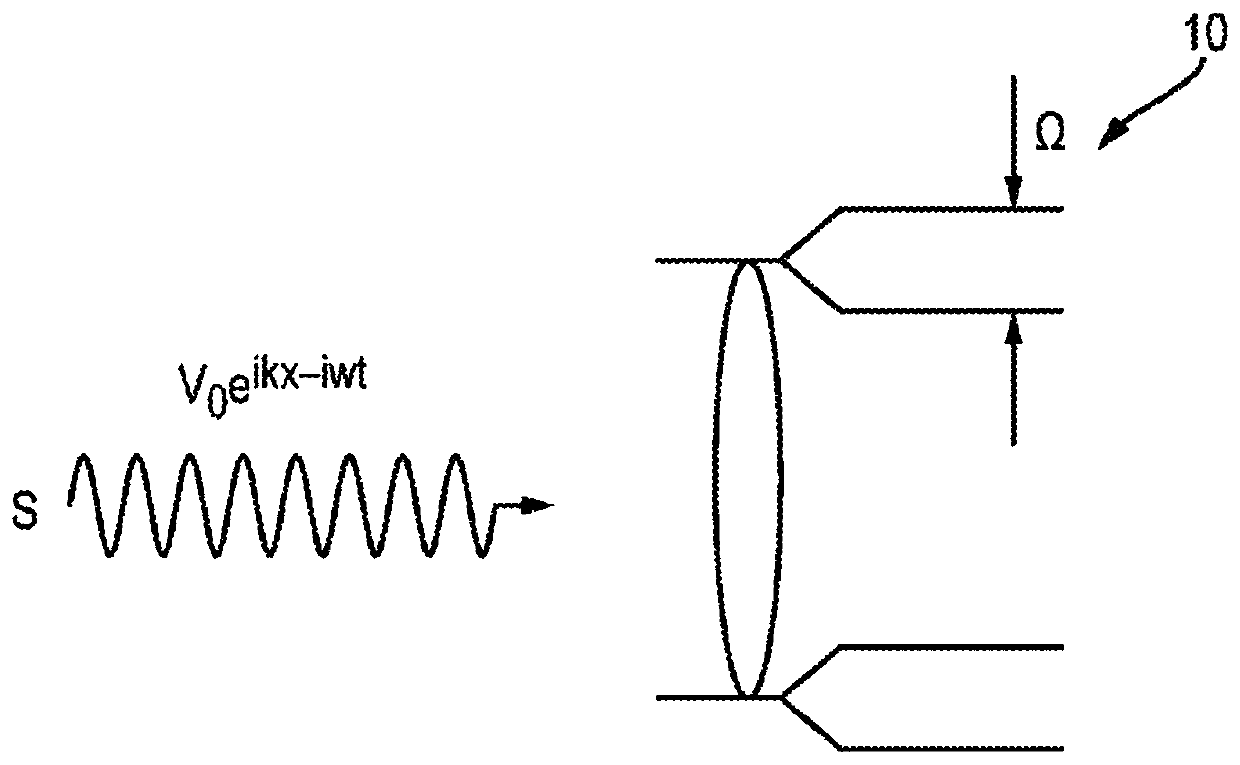
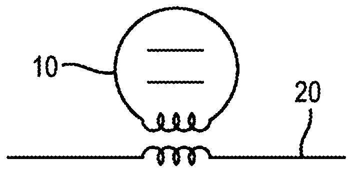
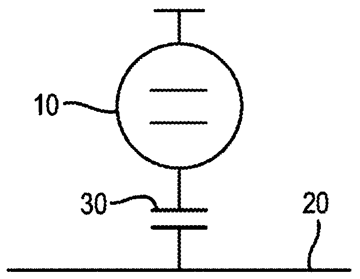
[0051] Embodiments of the present invention provide a quantum system coupled to a transmission line for use as a quantum sensor of absolute power. Refer below figure 1 Further describe the working principle of the present invention. already used Figure 6 and Figure 7 A proof-of-concept was performed for the arrangement depicted in , which consists of superconducting artificial atoms coupled to a coplanar 1D transmission line. Artificial atoms have different coupling strengths, are highly nonlinear, and can be approximated as two-level systems.

[0052] Such as figure 1 As shown in , when the quantum two-level system 10 is irradiated by an electromagnetic wave S, only a part of the incident photons is absorbed, where the speed is Ω. An incident electromagnetic wave S guided along a transmission line couples to the two-level system 10 via the dipole moment μ:

[0053]

[0054]where I and V are the amplitudes of the inductively coupled or capacitively coupled two-level...


PUM


Abstract

A quantum power sensor comprising a two-level quantum system strongly coupled to a transmission line that supports a propagating wave. A method of measuring power in a transmission line, the method comprising: coupling a two-level quantum system to the transmission line; and determining the coupling and the Rabi frequency of the two-level system.

Description

technical field [0001] The present invention relates to power sensors, in particular to sensors for measuring the absolute power of microwave signals in cryostats. Background technique [0002] Many devices that operate at low temperatures, such as quantum devices and superconducting qubits, use or process microwave signals, ie signals with frequencies in the range of 1 GHz to 50 GHz. Such signals are transmitted through transmission lines. Advances in microwave superconducting circuits, especially for applications to quantum computing and quantum optics, require calibration of microwave lines and knowledge of the power applied to circuits at cryogenic temperatures. So far there is no method for measuring the absolute power of microwave signals in continuous transmission lines at low temperatures, eg less than 5K. US 2009 / 0289638 discloses a device for measuring the state of a qubit by measuring the power of a standing wave in a transmission line cavity supporting a single...

Claims


Application Information

Patent Timeline
IPC IPC(8): G01R29/08B82Y15/00G01R1/24
CPCG01R1/24G01R29/0878G01R21/00H01F38/14
Inventor 奥列格·弗拉基米罗维奇·阿斯塔菲夫赖斯·谢哈伊达罗夫弗拉基米尔·尼古拉耶维奇·安东诺夫特雷莎·克莱尔·霍尼加尔-德克瑞尼斯塞巴斯蒂安·埃里克·德格拉夫
Owner NPL MANAGEMENT
Learn More