Positioning device for cutting steel pipes

A technology of positioning device and steel pipe, which is applied in the direction of positioning device, clamping, support, etc., can solve the problems of vibration, affecting the quality of steel pipe cutting, affecting the cutting accuracy, etc., and achieves the effects of accurate positioning, convenient cutting and firm fixing

Inactive Publication Date: 2019-06-18
湖南古新合盈机电有限责任公司
View PDF0 Cites 1 Cited by
  • Summary
  • Abstract
  • Description
  • Claims
  • Application Information

AI Technical Summary

Problems solved by technology

[0003] However, the existing steel pipe cutting device still has certain defects in use. Although the existing steel pipe cutting device can cut the steel pipe, it will affect the accuracy of cutting due to vibration during the cutting process, and the existing steel pipe cutting device Due to the fixed position, it is not convenient to identify the length of the steel pipe, which affects the quality of steel pipe cutting

Method used


Image

  • Positioning device for cutting steel pipes
  • Positioning device for cutting steel pipes
  • Positioning device for cutting steel pipes

Examples


Embodiment Construction

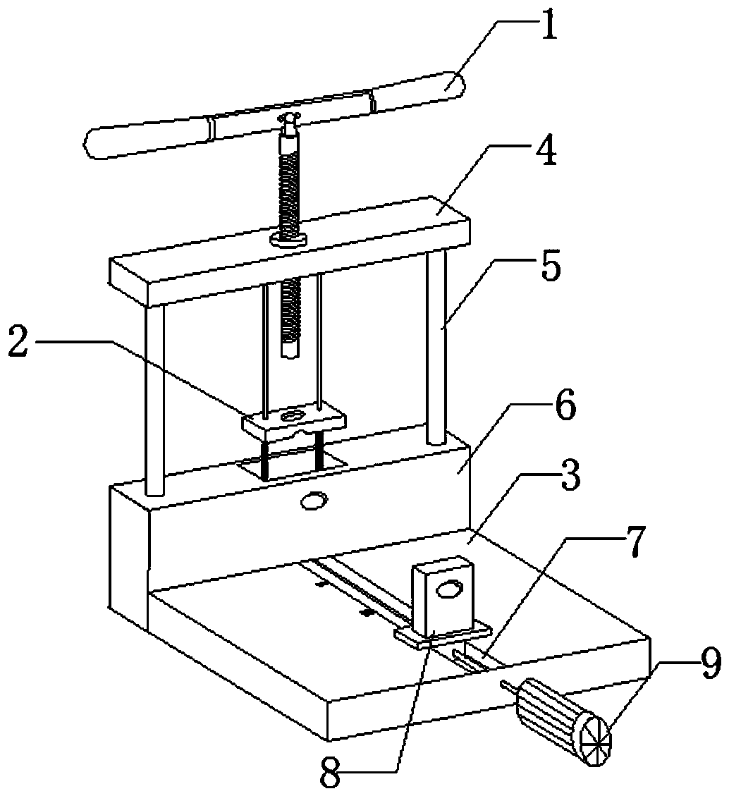
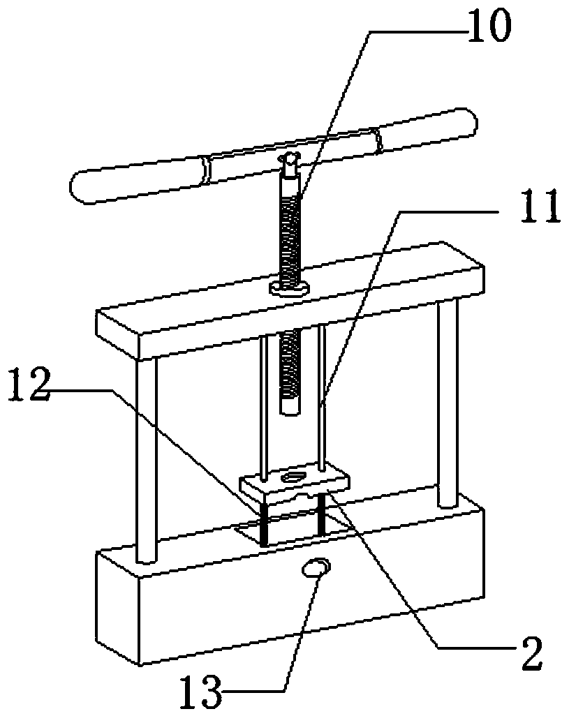
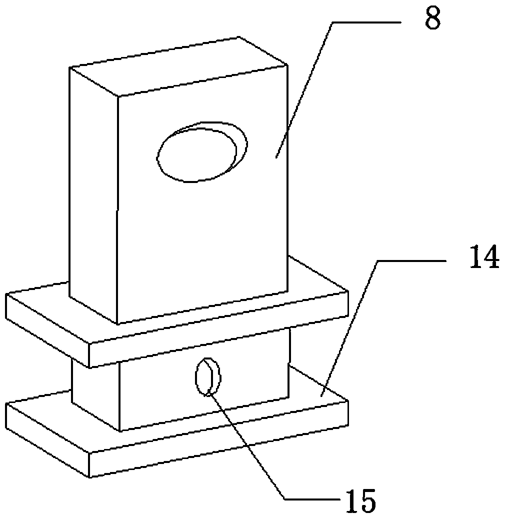
[0017] The technical solution of the present invention will be clearly and completely described below in conjunction with the accompanying drawings.

[0018] Such as Figure 1-4 As shown, the present invention includes a handle 1, a splint 2, a workbench 3 and a supporting plate 8, the handle 1 is provided with a support plate 4, the support plate 4 is welded below both sides of the pole 5, and the bottom of the pole 5 is welded to the base 6. The middle part of the workbench 3 is provided with a chute 7, one end of the chute 7 is provided with a blower 9, the middle part of the handle 1 is engaged with the screw 10, both sides of the screw 10 are provided with iron rods 11, and the bottom of the iron rod 11 is provided with a spring 12 The middle part of the base 6 is provided with a clamping hole 13, the bottom of the supporting plate 8 is welded with a clamping plate 14, the top of the clamping plate 14 is provided with an air inlet 15, the middle of the clamping plate 2 is...


PUM


Abstract

The invention discloses a positioning device for cutting steel pipes. The positioning device comprises a handle, a clamping plate, a worktable, a support plate, a strut, a base, a sliding groove, a support plate, an air blower, a screw, an iron rod, a spring, a clamping hole, a clamping plate, an air inlet hole, a screw hole and a clamping groove. The positioning device is provided with the clamping plate, a user can push the clamping plate to move by screwing the handle, the steel pipes are clamped through the clamping groove in the clamping plate, fixation of the steel pipes is facilitated,and cutting is more convenient to achieve; the support plate is arranged and is clamped into the sliding groove, and therefore the support plate can slide on the sliding groove back and forth, the user can identify the lengths of the steel pipes according to the scale on the worktable, and the steel pipes are cut more accurately; and the air blower is arranged, and therefore the air blower can beused for blowing chippings generated in the cutting process out of the sliding groove, and the condition that the chippings are accumulated in the sliding groove and sliding of the support plate is influenced are prevented. The positioning device has the characteristics of being firm in fixation and accurate in positioning.

Description

technical field [0001] The invention relates to a steel pipe cutting device, in particular to a positioning device for steel pipe cutting. Background technique [0002] The steel pipe is used to transfer fluid and powder, exchange heat and produce mechanical parts and containers, what's more it's a kind of economical steel. Using steel pipes to manufacture building structure grids, pillars and mechanical supports can reduce weight and realize factory-like mechanized construction. The use of steel pipes to manufacture highway bridges can not only save steel and simplify construction, but also greatly reduce the area of ​​the protective layer, saving investment and maintenance costs. [0003] However, the existing steel pipe cutting device still has certain defects in use. Although the existing steel pipe cutting device can cut the steel pipe, it will affect the accuracy of cutting due to vibration during the cutting process, and the existing steel pipe cutting device Due to...

Claims


Application Information

Patent Timeline
Patent Type & Authority Applications(China)
IPC IPC(8): B23Q3/06B23Q11/00B23Q17/20
Inventor 赵耀
Owner 湖南古新合盈机电有限责任公司
Why Eureka
Try Eureka