Welding method for electrical appliance display device

A technology of a display device and a welding method, which is applied to the welding field of electrical display devices, can solve the problems of different sizes of gaps, stress concentration, poor appearance, etc., and achieves the advantages of ensuring connection firmness, preventing gap overflow, and increasing the accommodating range. Effect

Active Publication Date: 2019-06-18
HEFEI HAIER DRUM WASHING MASCH CO LTD +1
View PDF5 Cites 0 Cited by
  • Summary
  • Abstract
  • Description
  • Claims
  • Application Information

AI Technical Summary

Problems solved by technology

[0005] The offset of the display structure leads to uneven gap between the display structure and the installation structure, the size of the gap is different, and the appearance is poor, which affects the overall aesthetics and affects the use of customers
[0006] Over-soldering will lead to overflow of melt glue, which can be seen in the gap between the display structure and the installation structure, which affects the overall aesthetics, and it is easy to cause adhesion where it should not stick, which in turn causes problems such as stress concentration, reducing service life
[0007] Additionally, some installation structures such as Figure 7 As shown, since the parting surface is set on the back of the installation structure, the draft angle becomes larger and larger from the back of the installation structure to the front, and then the gap between the installation structure and the display structure seen in the appearance is large, causing the user's visual The effect is poor, and because of the draft angle, the gap between the installation structure and the display structure in some positions is small, and it is very likely that a large area of ​​the installation structure and the display structure will be adhered, and stress concentration will easily occur at the adhesion, reducing the display. service life of the structure

Method used


Image

  • Welding method for electrical appliance display device
  • Welding method for electrical appliance display device
  • Welding method for electrical appliance display device

Examples


Embodiment 1

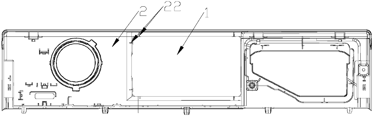
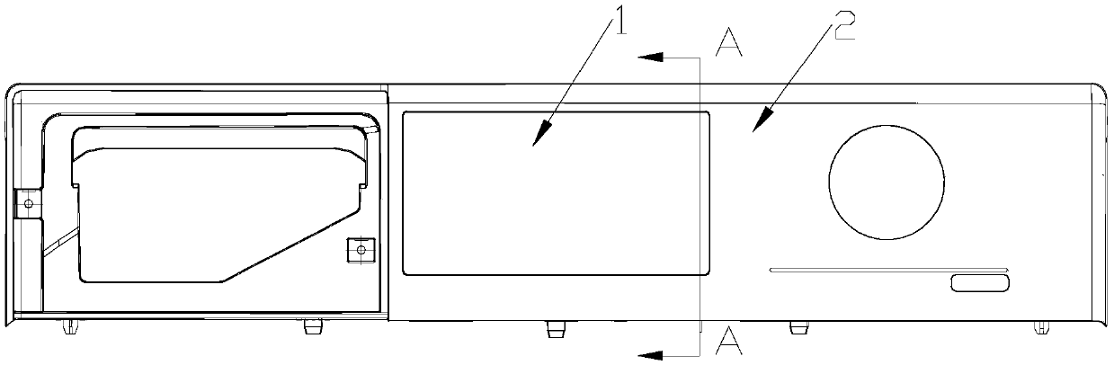
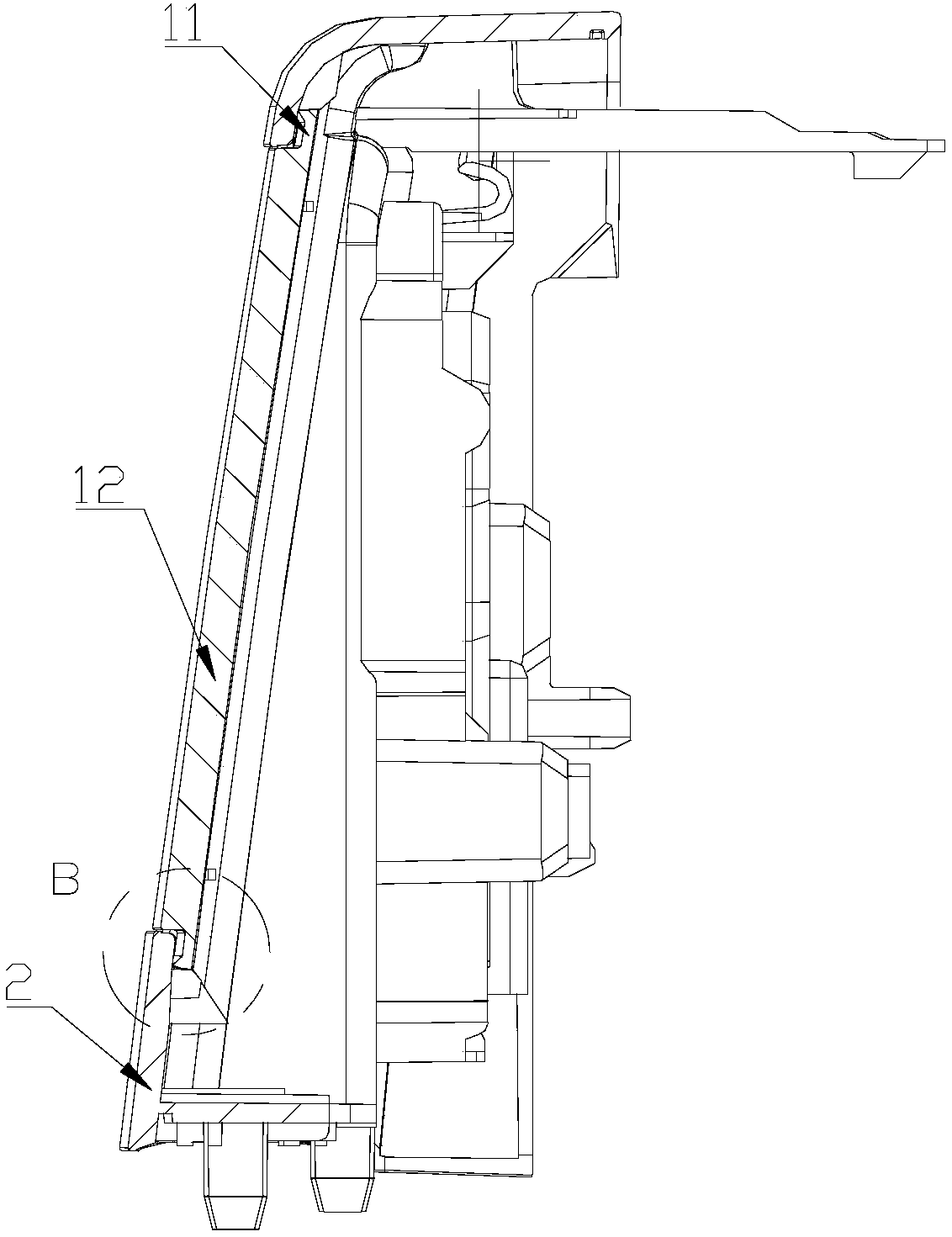
[0042] Such as Figure 1-Figure 6 As shown, a welding method for an electrical display device, the electrical display device includes a display structure 1 and a mounting structure 2, the display structure 1 is ultrasonically welded on the mounting structure 2, the mounting structure 2 includes a mounting hole, and the display structure 1 is at least partially fitted in the mounting hole, and the distance between the mounting hole on the front of the mounting structure 2 and the display structure 1 is smaller than the distance between the mounting hole on the back of the mounting structure 2 and the display structure 1.

[0043] In the above solution, the display structure 1 and the installation structure 2 of the electrical display device are connected and fixed by ultrasonic welding, which can not only ensure the firmness of the connection, but also ensure sufficient sealing, and protect the internal electrical components from water vapor, Damage from debris, etc. The insta...

Embodiment 2

[0056] In this embodiment, a welding method for an electrical display device, the electrical display device includes a display structure 1 and a mounting structure 2, the display structure 1 is ultrasonically welded on the mounting structure 2, the mounting structure 2 includes a mounting hole, the The display structure 1 is at least partially fitted in the installation hole, and the distance between the installation hole on the front of the installation structure 2 and the display structure 1 is smaller than the distance between the installation hole on the back of the installation structure 2 and the display structure 1 .

[0057] Compared with the first embodiment, the difference between the second side 24 and the display structure 1 extends farther toward the back of the installation structure 2 .

[0058] Further, the area of ​​the second side 24 parallel to the display structure 1 is greater than or equal to the area of ​​the first side 23 .

Embodiment 3

[0060] In this embodiment, a welding method for an electrical display device, the electrical display device includes a display structure 1 and a mounting structure 2, the display structure 1 is ultrasonically welded on the mounting structure 2, the mounting structure 2 includes a mounting hole, the The display structure 1 is at least partially fitted in the installation hole, and the distance between the installation hole on the front of the installation structure 2 and the display structure 1 is smaller than the distance between the installation hole on the back of the installation structure 2 and the display structure 1 .

[0061] Compared with Embodiments 1 and 2, the difference is that the distance between the side of the installation hole corresponding to the display structure 1 and the display structure 1 gradually increases from the front of the installation structure 2 to its back.


PUM


Abstract

The invention discloses a welding method for an electrical appliance display device. The electrical appliance display device comprises a display structure and a mounting structure, wherein the displaystructure is ultrasonically welded on the mounting structure; the mounting structure comprises a mounting hole; the display structure is at least partially arranged in the mounting hole in a sleevedmode; and a distance between the mounting hole in the front surface of the mounting structure and the display structure is smaller than that between a mounting hole in the back surface of the mountingstructure and the display structure. The welding method solves the problem that poor visual effect of a user is caused as a gap, seen from appearance, between the mounting structure and the display structure is great if a pattern withdrawing angle is gradually increased from the back surface of the mounting structure to the front surface of the mounting structure.

Description

technical field [0001] The invention relates to the field of the welding method of the electrical display device, in particular to a welding method of the electrical display device. Background technique [0002] In modern society, people rely more and more on electrical appliances in life, work, study, industry and other scenarios. In particular, household appliances used in daily life are becoming more and more indispensable in people's daily life. Generally, electrical appliances that require human-computer interaction will include an interactive interface. The outer layer of the interactive interface is usually a transparent display structure. For example, household appliances generally include a large user interface, and the outer layer of the interface is a transparent display. Structure, the display structure is generally a display screen, which is used for light transmission display, protection of internal electrical components, and pattern information of the interac...

Claims


Application Information

Patent Timeline
Patent Type & Authority Applications(China)
IPC IPC(8): B29C65/08
Inventor 黄涛程宝珍李丽萍
Owner HEFEI HAIER DRUM WASHING MASCH CO LTD
Why Eureka
Try Eureka